Stroboscope Project Uses Optical Drive Motor And Arduino

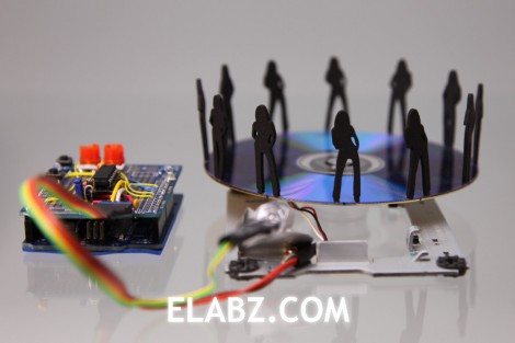
In the quest for a diy laser cutter made from DVD burner parts (that hack’s still in the works) this guy ended up with a junk box full of optical-drive leftovers. He put some of that surplus to good use by building this stroboscope. As the media spins, the white LED just out of focus in the foreground strobes to freeze the little black figure in the same place. The effect, as seen in the video after the break, is a dancing figure created by the optical illusion.

This is the same concept as that amazing 3D rowing skeleton build, but scaled down greatly. Each of the silhouettes seen above are slightly different, showing one pose that makes up a frame of the overall animation. They’re laser cut, but some careful paper-craft could probably accomplish the same thing. Assuming you could keep them from warping when spinning at high speeds.

Continue reading “Stroboscope Project Uses Optical Drive Motor And Arduino”
Experimenting With An Air Muscle And Sensor Feedback

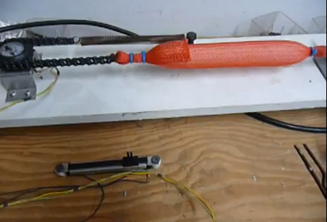
Check out this setup that [Ruenahcmohr] is using in his air muscle experiments. The orange mesh contains an air bladder that is connected to a hose on the right side. The bladder can be filled, or emptied with two solenoid valves not seen here (but you can get a good look in the video after the break). The muscle attached to chain on the other end and is kept under constant tension by a spring. The chain bends 180 degrees around a gear which is connected to a potentiometer. This gives feedback to the ATmega32 which controlling the whole thing. This way, the slider seen above can be used to control the apparatus.

We don’t know if [Ruenahcmohr] has a use in mind for this setup, but it certainly looks promising! We’ve seen these air muscles used for haptic feedback before, but right now we’re drawing a blank when it comes to ideas. What would you use it for?

Continue reading “Experimenting With An Air Muscle And Sensor Feedback”

TI Launchpad Adds Computer Control To A Robot Arm

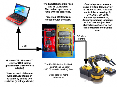
[Eric Gregori] had an OWI535 toy robotic arm. Although cheap (coming it at around $30) the arm is only set up to be used via a wired control box. [Eric] knew he could do better by adding computer control via a TI Launchpad and motor driver peripheral.

The arm has shoulder, elbow, and wrist joints, a rotating base, and a gripper. All of these are actuated by 3V DC motors and have just two control wires. [Eric’s] motor driver add-on for the Launchpad works great in this case. It’s got three FAN8200 dual motor driver chips on board so it can control up to six motors. Once he made the hardware connections it’s just a matter of sending the commands to the Launchpad via its USB interface, but you will also need to use a larger microcontroller than comes with the Launchpad. Here he’s chosen an MSP430G2553.

In order to make things a little bit more fun he also wrote a GUI for controlling the arm from the computer. He used RobotSee, a programming language that lets you use an image of the hardware, and overlay the controls on top of it. Now he just needs to make this into a web interface and he can have a smartphone controlled crane game.

Don’t forget to check out the video after the break. Continue reading “TI Launchpad Adds Computer Control To A Robot Arm”

A Real, Laser-based 3D Display

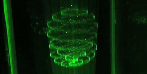
3D display technology is fairly limited. Most 3D displays out there rely on either prisms refracting light from a normal flat-panel display, or shooting lasers into some sort of space-filling device. A few researchers in Japan went with a more unconventional method of making a 3D display that actually lives up to the promises of the displays seen in Star Wars.

From the coverage of this display we’ve found, the green laser demonstration is a scaled-down version that uses water as the display medium. There’s a short clip that shows a red, green, and blue laser projecting a few white voxels into mid-air. The video of both these demonstrations is a bit jumpy, but that’s probably because of the difference in frame rate between the display and camera.

We’re not really sure how the “plasma excitations of air molecules with focused beams” actually work, or even how to control 50,000 of these dots at 15 frames per second. If you’ve got any idea how to build one of these guys, leave a note in the comments.

Continue reading “A Real, Laser-based 3D Display”

An Exercise In Servo Voice Control With Android

voice-controlled-android-lock

[Shazin] had some free time on his hands, so he settled in to do something he had been meaning to for a while – learn Android programming. He went an indirect route, and ended up using the Scripting Layer for Android (SL4A), which gave him a head start on the process. Sitting in between the Android API and scripting languages such as Python, SL4A allowed him the ability to apply something he was already familiar with to the Android environment.

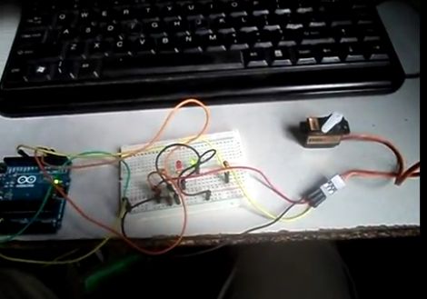
He thought it would be cool to try building a door entry system which relied on voice commands to lock and unlock. Using the Google Voice API for Android and an Arduino, he built a small Python application that allows him to toggle a servo simply by talking into his phone.

The application on his phone communicates with an Arduino over WiFi, once Google Voice has decoded the command [Shazin] is giving. The Arduino controls a servo, which in theory could control the locking mechanism on a door.

After a bit of tweaking and some added security, his proof of concept could definitely come in handy.

Check out the short video below to see [Shazin’s] voice-controlled servo in action.

Continue reading “An Exercise In Servo Voice Control With Android”

This Giant Hand Made LED Matrix Must Be Ours!

giant-led-matrix

[Martin] wrote in to share a project his company has been working on for some time, a gigantic 1470 pixel LED wall. The group provides lighting for clubs, parties, etc, and their hand-built LED matrix is always certain to be the hit of the show.

The amazing matrix was designed from the ground up and built by hand in [Martin’s] living room. They designed small 32x32mm “pixel” boards, each of which features 6 PLCC6 RGB LEDs driven by a single WS2801 LED controller. The PCBs were populated by hand and each one was reflowed in a small pizza oven that [Martin] owns. After the pixels were completed, they were attached to aluminum bar and combined to build thirty 70x70cm frames which are connected together to form a giant matrix.

As you can see in the collection of videos below, the display is very impressive. We just hope that they will be compelled to release the schematics for their boards so that we can build one of these in the office.

Continue reading “This Giant Hand Made LED Matrix Must Be Ours!”

Gridrunner: A Custom Part For Measuring In Eagle CAD

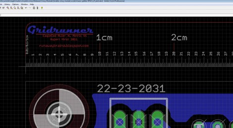
[Koogar] came up with a useful tool for checking the measurements of your layouts in Eagle CAD. He calls it the Gridrunner; a custom part that adds a 200mm ruler to your design. Tick marks are in 1/10th of a millimeter increments for great accuracy when used with the zoom feature of Eagle. Once you’ve got the layout just right, delete the ruler from your design and export it for fabrication. [Koogar] does mention that the beta version of Eagle 6 has a new measuring tool, but he still thinks the Gridrunner offers some things that the built-in tool doesn’t. See just how handy it is in the video after the break. The measuring starts about 1:40 into it.

We found it interesting that [Koogar] is using Eagle for quite a bit more than PCB design. We’ve used it for laying out a drilling template for face plates before, but he’s going far beyond that. He uses the library editor to recreate the parts of his CNC machine which he says are then really easy to align. From there, he exports the CAM files for mounting brackets. Do you use Eagle for something other than PCB design? Let us know about it by leaving a comment. Continue reading “Gridrunner: A Custom Part For Measuring In Eagle CAD”