Umbrella Antenna Protects You From Rain, But Not The Way You Think

You never know when you’ll be called upon to [MacGyver] your way out of an emergency. We can’t imagine what kind of situation would call for whipping up a satellite ground station for NOAA weather satellites from junk, but hey, it could happen.

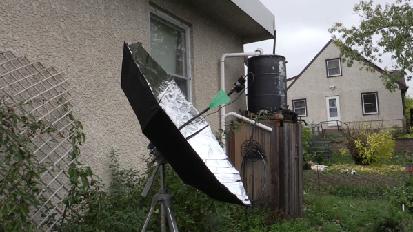
And when it does, you’ll be ready — as long as you have an umbrella, some foil tape, and various bits and bobs like wire and an RTL-SDR dongle. That’s what [saveitforparts] used for his field-expedient build, at least in the first instance; as you can imagine, builds like this take a lot of tweaking to get right. The umbrella and foil tape form the main reflector for the antenna, with a pie tin, a scrap of wire, and some random twigs being used to build the antenna’s helical feed. Attached to a SAWbird LNA/filter and an RTL-SDR plugged into a dodgy second-hand phone, he was able to get at least some kind of data from one of the GOES satellites, but it wasn’t great.

Switching the feed to a commercially available log periodic antenna worked much better, with some partial decodes of weather map data. Actually, getting anything at all with a setup like this is impressive enough for us to call it a win. It shows that the umbrella approach to antennas is valid; but then again, we already knew that.

Continue reading “Umbrella Antenna Protects You From Rain, But Not The Way You Think”

A 3D Printed Grinder For Printed Lens Blanks

When one thinks of applications for 3D printing, optical components don’t seem to be a good fit. With the possible exception of Fresnel lenses, FDM printing doesn’t seem up to the job of getting the smooth surfaces and precision dimensions needed to focus light. Resin printing might be a little closer to the mark, but there’s still a long way to go between a printed blank and a finished lens.

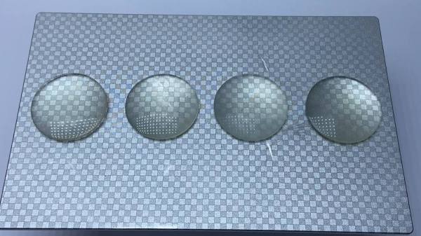
That gap is what [Fraens] aims to fill with this homebrew lens grinding machine. It uses the same basic methods used to grind and polish lenses for centuries, only with printed components and lens blanks. The machine itself consists of a motorized chuck for holding the lens blank, plus an articulated arm to hold the polishing tool. The tool arm has an eccentric drive that wobbles the polishing tool back and forth across the blank while it rotates in the chuck. Lens grinding requires a lot of water and abrasive, so a large bowl is provided to catch the swarf and keep the work area clean.

Lens blanks are printed to approximately their finished dimensions using clear resin in an SLA printer. [Fraens] spent a lot of time optimizing the printing geometry to minimize the number of print layers required. He found that a 30° angle between the lens and the resin pool worked best, resulting in the clearest blanks. To polish the rough blanks, a lapping tool is made from polymer modeling clay; after baking it dry, the tool can hold a variety of pads and polishing compounds. From there it’s just a matter of running the blank through a range of abrasives to get the desired final surface.

Are the lenses fantastic? Well, they’re probably not going to make it into fine optical equipment, but they’re a lot better than you might expect. Of course, there’s plenty of room for improvement; better resins might result in clearer blanks, and perhaps degassing the uncured resin under vacuum might help with bubbles. Skipping the printed blanks and going with CNC-machined acrylic might be worth a try, too.

Continue reading “A 3D Printed Grinder For Printed Lens Blanks”

Tech In Plain Sight: What Does A Yellow Light Mean?

Ghigleri’s traffic light

The traffic light is a ubiquitous feature of modern life and is quite old — dating back to 1868 London, although that device was a modified railroad semaphore operated by a policeman, but it was the same idea. The initial test of the signal proved disastrous.

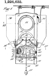
The semaphore had gas lamps to illuminate the signs in the dark. A gas leak caused one of the lamps to explode, badly burning the operator and ending the nascent invention for a while. In 1910, American inventor Ernest Sirrine worked out an automatically controlled traffic signal. Two years later, Lester Wire, a police officer, developed a different version powered by overhead trolley wires to light the signal. A 1917 patent by William Ghiglieri also had two lights — red and green. But where was the yellow light?

Continue reading “Tech In Plain Sight: What Does A Yellow Light Mean?”

Probably The Largest Selfie Camera In The World

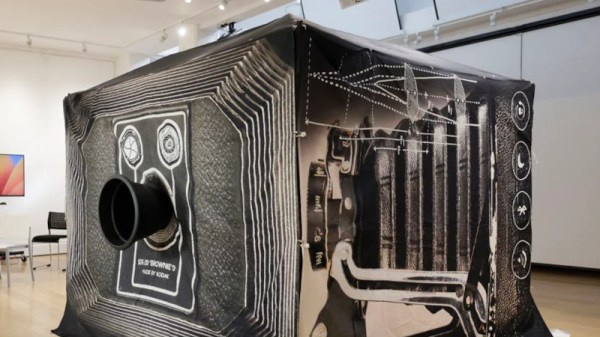
Most readers will have some idea of how a camera works, with a lens placed in front of a piece of film or an electronic sensor, and the distance between the two adjusted until the images is in focus. The word “camera” is a shortening of “camera obscura”, the Latin for “dark room”, as some early such devices were darkened rooms in which the image was projected onto a rear wall. [David White], a lecturer at Falmouth University in the UK has created a modern-day portable camera obscura using a garden gazebo frame, and uniquely for a camera obscura, it can be used to take selfies.

As might be expected the gazebo frame covered with a dark fabric forms the “room”, and the surface on which the image is formed comes from a projection screen. The lens is a custom-made 790 mm f/5.4, not exactly the type of lens found off-the-shelf. The selfie part comes from a Canon digital camera inside the gazebo focused on the frame, using its Wi-Fi control app a subject can sit at the appropriate point in front of the lens and take the selfie as they see fit.

The resulting images have a pleasing ethereal feel to them, and while it’s definitely not the most practical taker of snaps it’s still very much a camera to be impressed by. We’d be curious to see how it would perform as a pinhole camera, and even though it’s nowhere near the 2006 record pinhole image taken using an abandoned US Marine Corps aircraft hangar we think it would still deliver when given enough light. Meanwhile this isn’t the first time we’ve shown you a camera obscura, here’s one using the back of a U-Haul truck.

Lessons In Mass Production From An Atari Punk Console

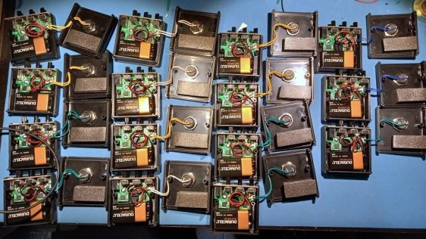
Sometimes the most interesting part of a project isn’t the widget itself, but what it teaches you about the manufacturing process. The story of the manufacturing scale-up of this Atari Punk Console and the lessons learned along the way is a perfect example of this.

Now, don’t get us wrong — we love Atari Punk Consoles. Anything with a couple of 555s that bleeps and bloops is OK in our books. But as [Adam Gulyas] tells the tale, the point of this project was less about the circuit than about the process of making a small batch of something. The APC was low-hanging fruit in that regard, and after a quick round of breadboarding to decide on component values, it was off to production. [Adam] was shooting for 20 units, each in a nice enclosure and a classy package. PCB assemblies were ordered, as were off-the-shelf plastic enclosures, which ended up needing a lot of tweaking. [Adam] designed custom labels for the cases, itself a fraught job; glossy label stock and button bezels apparently don’t mix.

After slogging through the assembly process, boxing the units for shipping was the next job. [Adam] sourced jewelry boxes just a bit bigger than the finished APCs, and rather than settle for tissue paper or packing peanuts, designed an insert to hold the units snugly. That involved a lot of trial and error and a little bit of origami-fu, and the results are pretty nice. His cost per unit came out to just a hair over $20 Canadian, including the packaging, which is actually pretty remarkable for such a short production run.

[Adam] includes a list of improvements for larger-scale runs, including ordering assembled PCBs, outsourcing the printing processes, and getting custom boxes made so no insert is needed. Any way you cut it, this production run came out great and teaches us all some important lessons.

Robots: How The Pros Keep Them Safe

Robotic safety standards are designed for commercial bots, but amateur robot builders should also consider ideas like the keepout zone where a mobile robot isn’t permitted to go or how to draw out the safety perimeter space for your experimental robot arm. After all, that robot arm won’t stop crushing your fingers because you built it yourself. So, it is worth looking at the standards for industrial robots, even if your aim is fun rather than profit.

The basics of this for fixed robots like robot arms are defined in the standard R15-06. You don’t need to read the full text (because it costs $325 and is *incredibly* tedious to read), but the Association for Advancing Automation has a good background on the details. The bottom line is to ensure that a user can’t reach into an area that the robot arm might move to and provide a quick and easy way to disable the motors if someone does reach in.

Robots that move, called Industrial Mobile Robots (IMRs) or Autonomous Mobile Robots (AMRs) bring in a whole new set of problems, though, because they are designed to move around under their own control and often share space with humans. For them, the standard is called R15.08. The AGV network has a good guide to the details, but again, it boils down to two things: make sure the robot is keeping an eye on its surroundings and that it can stop quickly enough to avoid injury.

The Linux Scheduler And How It Handles More Cores

Sometimes you read an article headline and you find yourself re-reading it a few times before diving into the article. This was definitely the case for a recent blog post by [The HFT Guy], where the claim was made that the Linux kernel has for fifteen years now been hardlocked into not scheduling for more than 8 cores. Obviously this caused a lot of double-checking and context discovery on both Hacker News and the Level 1 Techs forum. So what is going on exactly? Did the Linux developers make an egregious error more than a decade ago that has crippled Linux performance to this day? Continue reading “The Linux Scheduler And How It Handles More Cores”