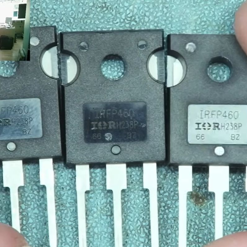
India Makes History With Chandrayaan-3 Landing

Yesterday, the Indian Space Research Organization’s (ISRO) Chandrayaan-3 spacecraft performed a powered soft-landing on the Moon, officially making India the fourth country to achieve a controlled descent to the lunar surface. Up to this point, only the United States, China, and the Soviet Union could boast successful landings on our nearest celestial neighbor.

Chandrayaan-3 Packed for Launch

What’s more, Chandrayaan-3 has positioned itself closer to the Moon’s south pole than any other mission in history. This area is of great interest to scientists, as there is evidence that deep craters in the polar region contain considerable deposits of frozen water. At the same time, the polar highlands receive almost constant sunlight, making it the perfect location to install solar arrays. These factors make the Moon’s south pole an ideal candidate for a future human outpost, and Chandrayaan-3 is just one of several robotic craft that will explore this area in the coming years.

But as is usually the case with space exploration, the success of Chandrayaan-3 didn’t come easy, or quickly. The ISRO started the Chandrayaan program in 2003, and launched the Chandrayaan-1 mission in 2008. The craft successfully entered lunar orbit and surveyed the surface using a wide array of instruments, many of which were provided by foreign space agencies such as NASA and the ESA. In 2019 the far more ambitious Chandrayaan-2 mission was launched, which included a lander and small rover. While the orbiter component of Chandrayaan-2 was a complete success, the lander crashed into the Moon’s surface and was destroyed.

With Chandrayaan-3 now safely on the surface of the Moon, there’s much work to be done in the coming days. The planned mission lifetime for both the lander and rover is a single lunar day, which equals just about two weeks here on Earth. After that, the vehicles will be plunged into a long stretch of frigid darkness which they likely won’t survive.

Continue reading “India Makes History With Chandrayaan-3 Landing”

A wooden frame with 64 green LEDs running a Game of Life simulation

Wooden CNC Sculpture Displays Conway’s Game Of Life

Conway’s Game of Life has been the object of fascination for computer hobbyists for decades. Watching the generations tick by is mesmerizing to watch, but programming the data structure and implementing the rules is also a rewarding experience, especially if you’re just getting acquainted with a new computing platform. Just as rewarding can be creating a nice piece of hardware to run the game on, as [SandwichRising] has just done: check out his beautiful wooden Game of Life implementation.

A set of PCBs implementing an 8x8 LED displayThe main part of his Game is a piece of poplar wood that was CNC routed to produce an 8×8 display adorned with neat chain-like shapes. The display consists of standard 5 mm green LEDs, but they’re not the things you see poking out the front of the wooden frame. Instead, what you’re seeing are 64 lenses made out of epoxy. [SandwichRising] first covered the holes with tape, then poured green epoxy into each one and waited for it to harden. He then took off the tape and applied a drop of UV-cured epoxy on top to create a lens.

All the LEDs are mounted on PCB strips that are hooked up to a central bus going to the main ATmega328P  microcontroller sitting on a separate piece of PCB. Whenever the system is powered on, the game is set to a random state determined by noise, after which the simulation begins. On such a small field it’s pretty common for the game to end up in a stable state or a regular oscillation, which is why the ATmega keeps track of the last few dozen states to determine if this has happened, and if so, reset the game to a random state again.

The source code, as well as .STL files for the PCBs and the frame, are available in the project’s GitHub repository. If woodworking isn’t your thing, there’s plenty of other ways to make neat Game of Life displays, such as inside an alarm clock, with lots of LEDS under a coffee table, or even with a giant flip-dot display.

Doppler Speed Sensor Puts FFT And AGC To Work

Some people hate to revisit projects that are done and dusted. We get that; it’s a little like reading a book you’ve already read when there are so many others to choose from. But rereading a book sometimes reveals subtle nuances you missed the first time around, and revisiting projects can be much the same, as with this new and improved Doppler radar speed sensor.

We seem to have been remiss in writing up [Limpkin]’s last go-around with the CDM324 microwave module, a 24-GHz transceiver that you can pick up on the cheap from the usual sources, but we’ve featured this handy little module in plenty of other projects. [Limpkin]’s current project uses the same module to create a Doppler speed sensor, but with a little more sophistication all around. Whereas the original used a simple comparator to output a square wave that’s proportional to the Doppler shift and displayed the speed on a simple terminal session, version two takes a different tack.

First, [Limpkin] opted to implement the whole sensor in hardware. The front end is quite different — an op-amp with 84 dB of gain followed by an automatic gain control (AGC) stage built from a MAX9814 microphone preamp. Extraction of the speed from the module output is left to an STM32F301 running an FFT algorithm on the signal coming out of the analog circuit, which essentially picks out the biggest peak in the spectrum and calculates the Doppler shift from that, displaying the results on an LCD display.

Of course, as a [Limpkin] project, there’s a lot more to it than just that. The write-up is very detailed, going down a few enjoyable rabbit holes like characterizing the amplification chain and diving into the details of Johnson-Nyquist noise to chase down stray oscillations. There’s some great stuff here, and it’s well worth a deep read; there’s also the video below that lets you see (and hear) what’s going on.

Continue reading “Doppler Speed Sensor Puts FFT And AGC To Work”

This Car Has Wooden Performance

If you were to take a look at the car parked closest to where you are sitting, there’s an overwhelming probability that its main structural parts are made of steel. A few might be aluminium and fewer still composite materials, but by and large that’s it for automotive structures. This hasn’t stopped the inventive Russians at [Garage 54] from experimenting though, and in their latest they’ve made a car with a chassis made of wood. Not carefully sawn and assembled wooden structural components, oh no. These are wooden tree trunks and branches.

Of course it’s an opportunity for them to run wild on their very successful schtick of the crazy Eastern European YouTuber, but behind that it’s entertaining to watch how they adapt a drive train — taken we’re guessing from the FIAT 124-derived Zhiguli, or Lada as most of us would know it — to such an unconventional chassis. A lot of wire binding is used, and even then the car has a lot of the flexible about it. We’re not so sure about the differential without oil or indeed the front suspension that appears to be developing a lean, but they do manage to take it out of the forest and onto the road.

Are unconventional and definitely-not-road-legal motors your thing? Here’s another, courtesy of some Dutch lads.

Continue reading “This Car Has Wooden Performance”

Custom Font Generation Means Boss Embossing

[Attoparsec] loves learning languages, but says they have a hard time retaining anything. We find that hard to believe given the number of tongues that [Attoparsec] was able to translate into embossing plastic. That’s right, this project is about making custom font wheels for an embosser, formerly known as a label maker.

If you think this seems like a finicky and perhaps lengthy mission to undertake, you’re right. In case you’re unfamiliar, ye olde embosser uses both a positive and a negative of each glyph in order to impress the sticky-backed plastic strip. It all started when [Attoparsec] found out about the Dymo 1595, which comes with font wheels for both Japanese hiragana and katakana in addition to English.

After sacrificing the English wheel, it was time to model the wheel part itself. That was easy enough, but the characters themselves were another story. Because of how the thing works, the negative has to be bigger than the positive to provide enough room for the tape. After trying to achieve the right draft angle on the characters in several CAD packages, [Attoparsec] was told that it should be fairly easy in OpenSCAD, and it was.

Printing in resin took about five hours to do both wheels at once. Once [Attoparsec] had the workflow down, they were off to the races. In this video alone, they made Old English, Esperanto, the International Phonetic Alphabet, an alphabet created by playwright George Bernard Shaw, Palm Pilot input script, and of course, Tolkein’s Tengwar. Be sure to check out the video after the break.

Tired of turning the wheel of your embosser to make labels? Automate the process with a stepper motor or two.

Continue reading “Custom Font Generation Means Boss Embossing”

Pen Plotter Uses Polar Coordinates

To keep track of a location in a two-dimensional space, two measurements are needed. Most of the time, we would naturally think to do this by the Cartesian method, measuring position along one axis and then again along a second axis. But this isn’t the only way of keeping track of position. Polar coordinates, where the distance from the origin and an angle are used as the two measurements, works just as well, and sometimes can be a preferred method. This pen plotter tosses the expected Cartesian methodology we would typically expect in favor of this polar system.

The first prototype that [André] built was a good proof of concept. A pen attached to a movable carriage on a single rotating arm produced passable drawings, but as all prototypes go this one needed some refinement. Limit switches at the ends of the table, as well as within the arm, served to orient the plotter so that it didn’t manually need to be zeroed out every time. A linear actuator was added to give finer control over the pen’s pressure on the table, and finally an encoder was added to the base of the plotter to more accurately correct positional errors in the rotating arm mechanism.

With everything said and done, the polar coordinate plotter seems to work just as well as its Cartesian cousins might, orienting it like this has some advantages as well. Specifically, it is more adapted to drawing curves or circles than an X-Y device might be able to, like we saw with this similar sand-drawing plotter. Also, if allowed to rotate its entire 360-degree reach instead of just the 90 degrees shown in the video, a machine like this could theoretically reach a wider workspace more easily than other plotters.

Continue reading “Pen Plotter Uses Polar Coordinates”

DIY Pan And Tilt Camera Mount

Pan and tilt mounts have a number of uses that can increase the functionality of various types of cameras. Security cameras can use them to adjust the field of view remotely, astronomers can use them as telescope mounts to accurately track celestial objects, and of course photographers and videographers can use them to add dynamic elements to shots. But getting the slow, smooth, and reliable movement isn’t as simple as slapping some servos on a tripod. So unless you want to break the bank for a commercial mount, this DIY pan and tilt mount might be the way to go.

The mount is built largely out of 3D printed parts and a few fairly common motors, belts, pulleys, and bearings. The movements are controlled using stepper motors, and there are two additional systems built in so that focus and zoom can be controlled through the system as well. The software controlling it all is open-source and  available on GitHub, and controls the mount remotely through a network connection. It’s also designed to use the readily-available ESP32 chip, making it overall fairly adaptable.

The system doesn’t slouch on features, either. It can move from one point to another with various programmable speeds, has a key sequencer for more complex movements, and can accommodate the needs of stop motion animators as well. It’s an impressive build that should be accessible to plenty of photographers with a 3D printer and the right parts, but photography and astronomy aren’t the only reasons to use a pan and tilt mount. Check out this one that brings some sunlight to a shaded room.