Easyeda2KiCad: Never Draw A Footprint Again

What if I told you that you might never need to draw a new footprint again? Such is my friend’s impression of the tool that she’s shown me and I’m about to show you in turn, having used this tool for a few projects, I can’t really disagree!

We all know of the JLCPCB/LCSC/EasyEDA trio, and their integration makes a lot of sense. You’re expected to design your boards in EasyEDA, order the components on LCSC, and get the boards made by JLCPCB. It’s meant to be a one-stop shop, and as you might expect, there’s tight integration between all three. If there wasn’t, you’d be tempted to step outside of the ecosystem, after all.

But like many in this community, I use KiCad, and I don’t expect to move to a different PCB design suite — especially not a cloud one. Still, I enjoy using the JLCPCB and LCSC combination in the hobby PCB market as it stands now, and despite my KiCad affinity, it appears that EasyEDA can help me after all!

Continue reading “Easyeda2KiCad: Never Draw A Footprint Again”

Hacking Fake Food

Ever seen a restaurant where they display fake models of the food on the menu? We never thought much about how shokuhin sampuru — the Japanese name — were made until we watched [Process X]’s video showing a 71-year-old artist creating food models. We aren’t sure what we — or you — would do with this information, but it is a striking process, and there must be something you could do with it. We suggest turning on the English captions, but you’d probably enjoy watching the unusual craftsmanship even with no words.

In years past, the food models were primarily made from wax, but since the 1980s, it is more common to use polyvinyl chloride, silicone, and resin. While some factories produce items, sometimes with a mold, single craftsmen like the one in the video still make up the largest part of the market.

We aren’t sure, but we think the material in the video is wax. We couldn’t help but think that some of this could have been 3D printed, but even with the finest resins and resolution, it probably wouldn’t be quite as artistic. We think wax is mainly underutilized in today’s tech. But there are some places it still shows up.

Continue reading “Hacking Fake Food”

Under The Sea: Optical Repeaters For Submarine Cables

Once a month or so, I have the privilege of sitting down with Editor-in-Chief Elliot Williams to record the Hackaday Podcast. It’s a lot of fun spending a couple of hours geeking out together, and we invariably go off on ridiculous tangents with no chance of making the final cut, except perhaps as fodder for the intro and outro. It’s a lot of work, especially for Elliot, who has to edit the raw recordings, but it’s also a lot of fun.

Of course, we do the whole thing virtually, and we have a little ritual that we do at the start: the clapping. We take turns clapping our hands into our microphones three times, with the person on the other end of the line doing a clap of his own synchronized with the final clap. That gives Elliot an idea of how much lag there is on the line, which allows him to synchronize the two recordings. With him being in Germany and me in Idaho, the lag is pretty noticeable, at least a second or two.

Every time we perform this ritual, I can’t help but wonder about all the gear that makes it possible, including the fiber optic cables running beneath the Atlantic Ocean. Undersea communications cable stitch the world together, carrying more than 99% of transcontinental internet traffic. They’re full of fascinating engineering, but for my money, the inline optical repeaters that boost the signals along the way are the most interesting bits, even though — or perhaps especially because — they’re hidden away at the bottom of the sea.

Continue reading “Under The Sea: Optical Repeaters For Submarine Cables”

Different Etching Strokes For Different PCBs, Folks

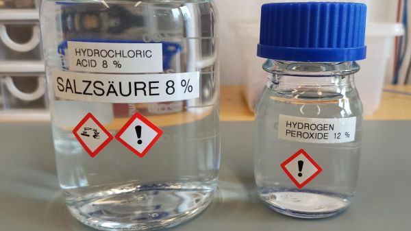
[Sebastian] probably didn’t think he was wading into controversial waters when he posted on his experimental method for etching PCBs (in German). It’s not like etching with hydrochloric acid and peroxide is anything new, really; it was just something new to him. But is it even possible these days to post something and not find out just how wrong you are about it?

Sadly, no, or at least so it appears from a scan of [Sebastian]’s tweet on the subject (Nitter). There are a bunch of ways to etch copper off boards, including the messy old standby etchant ferric chloride, or even [Sebastian]’s preferred sodium persulfate method. Being out of that etchant, he decided to give the acid-peroxide method a go and was much pleased by the results. The traces were nice and sharp, the total etching time was low, and the etchant seemed pretty gentle when it accidentally got on his skin. Sounds like a win all around.

But Twitter wouldn’t stand for this chemical heresy, with comments suggesting that the etching process would release chlorine gas, or that ferric chloride is far safer and cleaner. It seems to us that most of the naysayers are somewhat overwrought in their criticism, especially since [Sebastian]’s method used very dilute solutions: a 30% hydrochloric acid solution added to water — like you oughta — to bring it down to 8%, and a 12% peroxide solution. Yes, that’s four times more concentrated than the drug store stuff, but it’s not likely to get you put on a terrorism watch list, as some wag suggested — a hair stylist watchlist, perhaps. And 8% HCl is about the same concentration as vinegar; true, HCl dissociates almost completely, which makes it a strong acid compared to acetic acid, but at that dilution it seems unlikely that World War I-levels of chlorine gas will be sweeping across your bench.

As with all things, one must employ caution and common sense. PPE is essential, good chemical hygiene is a must, and safe disposal of spent solutions is critical. But taking someone to task for using what he had on hand to etch a quick PCB seems foolish — we all have our ways, but that doesn’t mean everyone else is wrong if they don’t do the same.

Continue reading “Different Etching Strokes For Different PCBs, Folks”

Reviving An 8-Inch Hard Drive From The 1980s

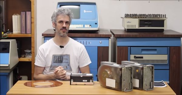
As part of the eternal quest within the realm of retrocomputing, storage devices can be one of the most challenging, especially when it comes to firmly obsolete hard drives, such as the CDC Finch drive. This compact 8″ HDD replaced the previous 14″ models with a form factor that was decidedly more portable. These Finch drives being 1980s technology that got run pretty hard before their retirement, it’s little wonder that they’d end up on the repair bench over at [Usagi Electric]

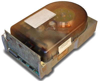
A CDC Finch hard disk drive, available in 8 to 32 MB for all your data storage needs. (Credit: Usage Electric)

Introduced in the early 1980s, the CDC Model 9410 Finch drive was unlike its 14″ predecessors in that it is a sealed unit, with maintenance-free air filtration. With the 14″ models you’d have both fixed and swappable platters, with far less consideration for dust exposure. This makes these Finch drives more touchy to work on, not unlike HDDs today, and adds to the excitement when repairing one of these old drives.

In this video, two differently broken Finch drives are discussed. Both appear to have an issue on the controller board, with one not responding to communications on the interface, while the other featuring a dead short on the interface pins. The first drive was brought back to life by replacing a dead SN75110 line driver IC, as well as a dead 7818 voltage regulator that was only outputting a sad 0.3 V.

Unfortunately, after half an hour of uptime and in the process of dumping data the drive errored out with a Not Ready, indicating that there are further issues on the controller board to fix. The good news here is that the platters appear to be pretty robust, but the controller boards on these old drives tend to develop issues over the years, something which will be further explored in upcoming videos.

Continue reading “Reviving An 8-Inch Hard Drive From The 1980s”

Enhance Your Enclosures With A Shadow Line

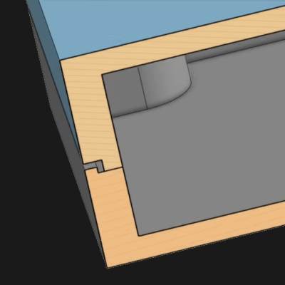
Some design techniques and concepts from the injection molding world apply very nicely to 3D printing, despite them being fundamentally different processes. [Teaching Tech] demonstrates designing shadow lines into 3D printed parts whose surfaces are intended to mate up to one another.

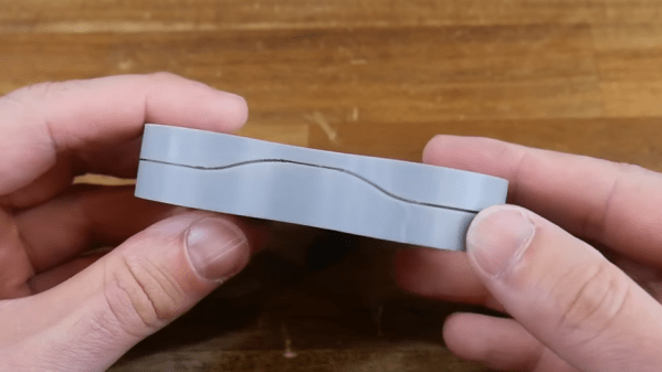
This is a feature mainly seen in enclosures, and you’ve definitely seen it in all kinds of off-the-shelf products. Essentially, one half of the part has a slight “underbite” of a rim, and the other half has a slight “overbite”, with a bit of a standoff between the two. When placed together, the combination helps parts self-locate to one another, as well as providing a consistent appearance around the mating surfaces.

Why is this necessary? When a plastic part is made — such as an enclosure in two halves — the resulting surfaces are never truly flat. Without post-processing, the two not-quite-flat surfaces result in an inconsistent line with a varying gap between them.

By designing in a shadow line, the two parts will not only self-locate to each other for assembly, but will appear as a much more consistent fit. There will be a clear line between the two parts, but no actual visible gaps between them. Watch the whole thing explained in the video, embedded below.

This isn’t the only time design techniques from the world of injection molding have migrated to 3D printing. Crush ribs have been adapted to the world of 3D printed parts and are a tried-and-true solution to the problem of reliably obtaining a tight fit between plastic parts and hardware inserts.

Continue reading “Enhance Your Enclosures With A Shadow Line”

Linux Containers The Hard Way

If you want to make containers under Linux, plenty of high-level options exist. [Lucavallin] wanted to learn more about how containers really work, so he decided to tackle the problem using the low-level kernel functions, and he shared the code with us on GitHub.

Containers are more isolated than processes but not quite full virtual machines. While a virtual machine creates a fake computer, a container is more like a fake operating system. Applications can run with their own idea of libraries, devices, and other resources, but it doesn’t try to abstract the underlying hardware.

Continue reading “Linux Containers The Hard Way”