This excellent content from the Hackaday writing crew highlights recurring topics and popular series like Linux-Fu, 3D-Printering, Hackaday Links, This Week in Security, Inputs of Interest, Profiles in Science, Retrotechtacular, Ask Hackaday, Teardowns, Reviews, and many more.
Plenty of materials take the heated edge of a laser beam quite well, but many others don’t. Some release toxic fumes; others catch fire easily. For all the materials that don’t cut well (PVC and FR4, we’re looking at you!) and for those that do (hello, acrylic and Delrin) they’re each reacting to the heat of the laser beam in different ways. Lucky for us, these ways are well-characterized. So let’s take a look at how a laser cutter actually cuts through materials.
[Tsvetan Usunov] has been Mr. Olimex for about twenty five years now, and since then, he’s been through a lot of laptops. Remember when power connectors were soldered directly to the motherboard? [Tsvetan] does, and he’s fixed his share of laptops. Sometimes, fixing a laptop doesn’t make any sense; vendors usually make laptops that are hard to repair, and things just inexplicably break. Every year, a few of [Tsvetan]’s laptops die, and the batteries of the rest lose capacity among other wear and tear. Despite some amazing progress from the major manufacturers, laptops are still throwaway devices.
Since [Tsvetan] makes ARM boards, boards with the ~duino suffix, and other electronic paraphernalia, it’s only natural that he would think about building his own laptop. It’s something he’s been working on for a while, but [Tsvetan] shared his progress on an Open Source, hacker’s laptop at the Hackaday | Belgrade conference.
Long ago, when I wanted a plywood sheet, I would go to the local big box hardware store and buy whatever was at the center of the optimization curve for cheapest and nicest looking. I would inevitably suffer with ultra-thin veneers on the top, ugly cores, unfinishable edges, warping, voids, and other maladies of the common plywood. One day I said enough is enough and bothered the salesman at my local lumber supply until he showed me one that wasn’t awful.
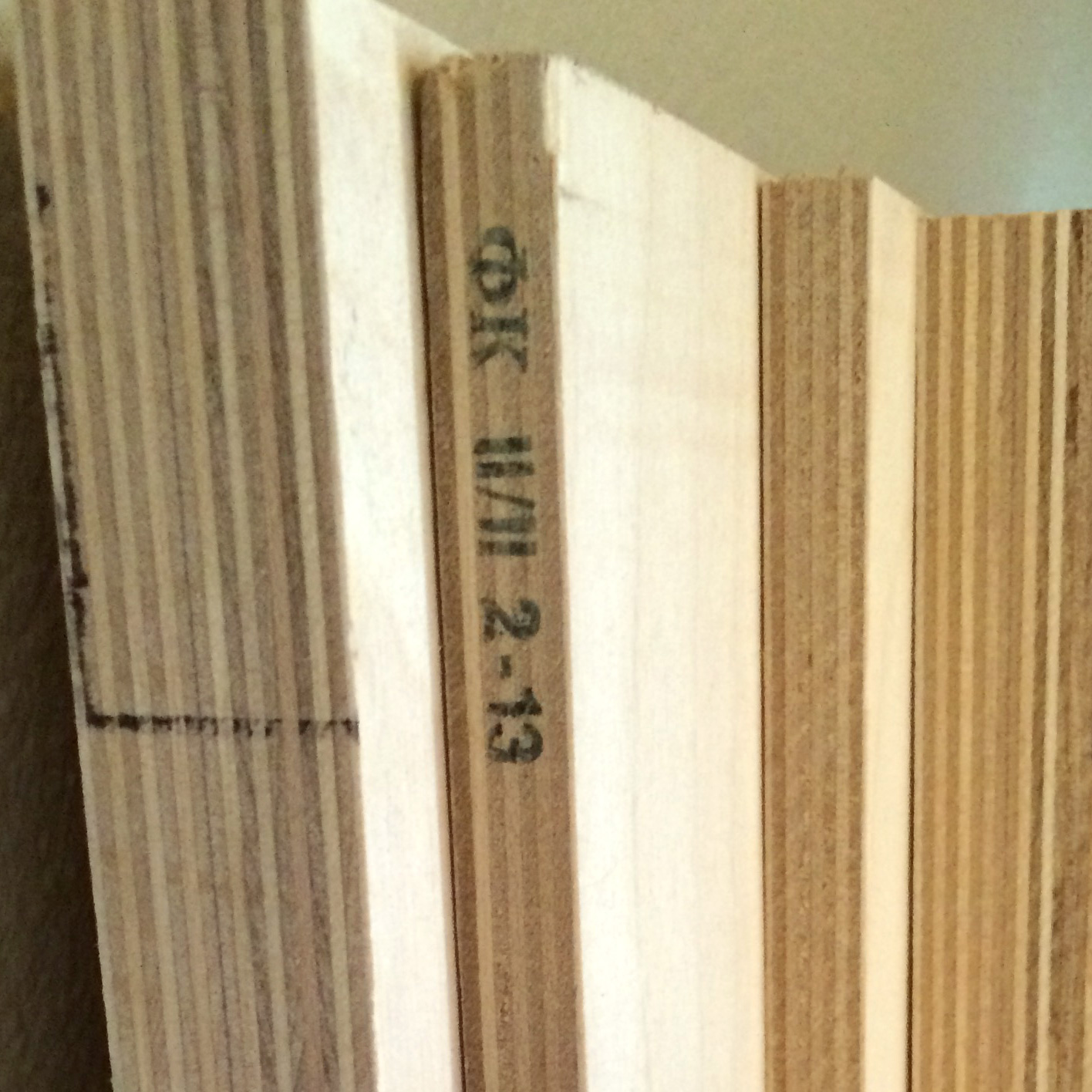
There are subtle clues that the Baltic Birch I’ve purchased is Russian.
Baltic birch differs from other plywoods in a few ways. Regular plywood is usually made locally from the cheapest possible core wood in alternating grain layers laminated together with a hardwood veneer on the top. There are interior and exterior grades. The exterior grades are usually made with a different glue, but don’t necessarily denote a higher quality or stability. Some of the glues used can be toxic. Wear a respirator. In normal plywood, the ATSM or BB standards only apply to the face veneers used to finish the product. The core can be of whatever quality is convenient for the manufacturer.
True Baltic Birch is made in the Baltic Region with the biggest producers being Russia and Finland. Outside of the US it is sometimes called Finnish Birch or Russian Birch plywood for this reason. It is made from only top quality birch veneers laminated together with no filler wood. It is also unique in the care taken to make sure each layer of the wood is patched so there are no voids. All Baltic Birch is made with exterior grade glue, and when properly sealed will work for outdoor applications. There are grades of Baltic birch for marine applications and exceptionally void free aircraft grade plywood at a much higher cost.
The easiest way to spot Baltic Birch if you’re American is its form factor. Baltic birch comes in 1525 x 1525 mm squares, which approximates to 5 ft x 5 ft. Some people have said that manufacturers have started to produce 4 ft x 8 ft sheets specifically for the North American market, but this information comes with a caveat that these are usually lower grades made locally or in China parading under the name. The metric form factor extends to the thicknesses of the sheets. In America they will be sold as inch, but fit pretty closely to a metric form.
3 mm ≈ 1/8″ (3 plies)
6 mm ≈ 1/4″ (5 plies)
9 mm ≈ 3/8″ (7 plies)
12 mm ≈ 1/2″ (9 plies)
18 mm ≈ 3/4″ (13 plies) – From [3] Ultimate guide to Baltic birch.
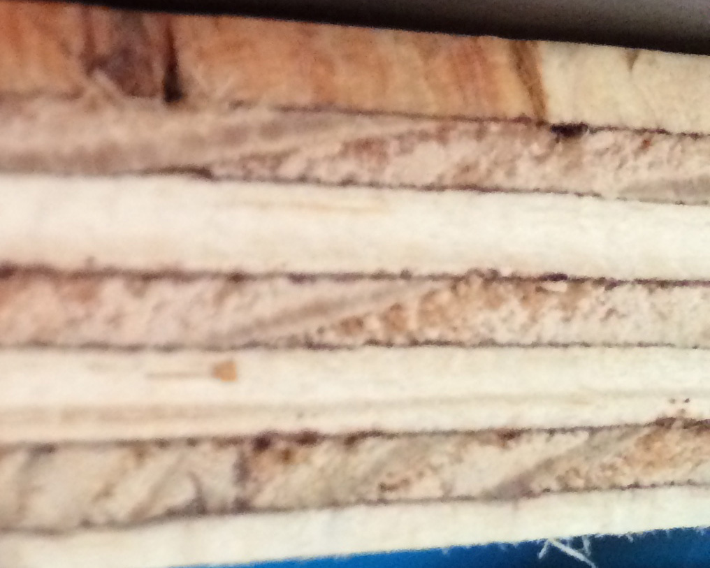
The core of regular hardware store plywood. Pretty bad in comparison.
There are some really nice practical features of Baltic Birch. One of my favorites is the absolute uniformity of the layers. This means that two pieces of birch can be laminated together and the seam between the two becomes indistinguishable. I’ve used this to make cases by CNC routing out the inside of a sheet of Baltic birch, drilling some holes for alignment pins, and then laminating the whole assembly together. We’ve covered a few readers who have had similar ideas. Since the layers are uniform you can also do interesting things when combined with a CNC router. For example, carefully milling away the layers you can get a topographic map of the object.
Baltic Birch is also significantly flatter and more stable than other plywood options. It is commonly the material used for fences on expensive tables saws. It moves less during temperature swings and changes in ambient moisture. This is one of the reasons it’s popular with fine furniture builders. This also makes Baltic birch a good option for home CNC builds, certainly better than MDF . Due to the higher quality wood and better manufacturing it is quite strong as well. It is a great structural wood.
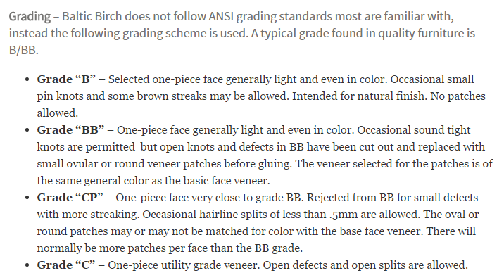
Explanation of the grading scale for Baltic Birch from [1] Dan’s hobbies.Baltic birch holds stains very well on both its faces and its edges. It’s as easy to paint and glue as any wood. As far as surface finish goes it’s important to note that as mentioned previously, Baltic Birch is graded to a different scale than regular plywood. The grades will determine how the face veneers are treated. B/B is the highest grade with both sides being defect free. B/BB is much more common and is what you are likely to find. I have not found C or CP grades in the US. My guess is that we have plenty of low grade plywoods to compete with it. It is likely found nearer to the areas where it is produced.
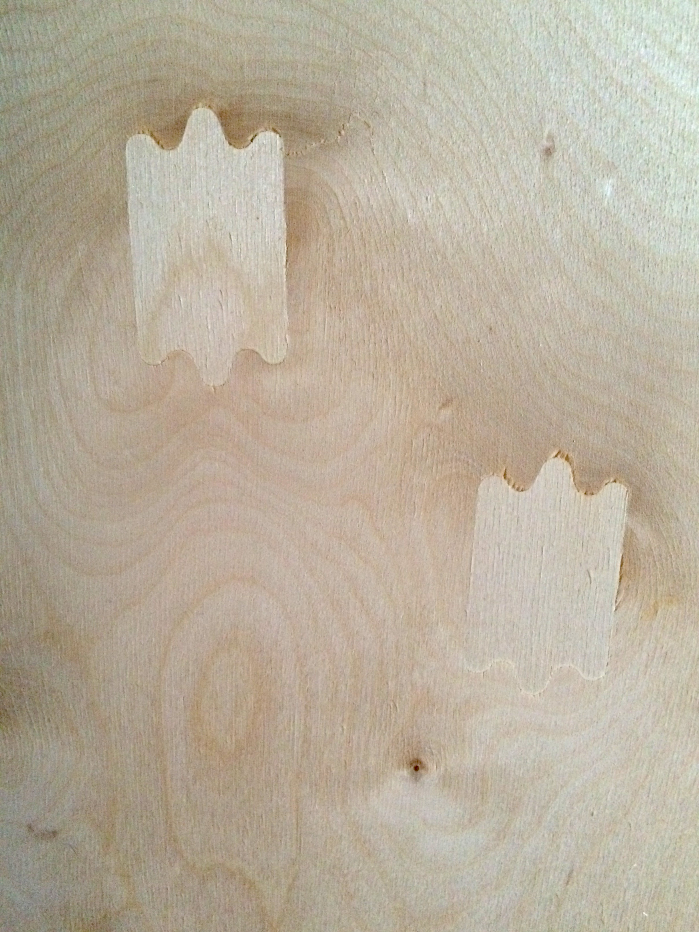
This is on the non-finishing side of a Baltic Birch panel. You can see the care taken to fix knots and voids. This will be done through the whole sheet. The face of the board will not have marks. This is a B/BB grade sheet. If it was B/B both sides would be without patches.
Baltic birch is more expensive than the regular grade stuff. So a sheet of ¾” thick Oak veneer plywood with a pine core, interior grade, from Lowes is about 35 US dollars where a similar sheet of 18mm Baltic Birch will run around 65 dollars.
I’ll still occasionally purchase a cheaper sheet of plywood when I have a non-critical application (like garage shelving), but when I am doing something precise or nice I’ll spend the extra on the birch plywood. While I love this material, I am by no means a wood worker. Have any of you had experience with this plywood? Is there an even better plywood out there?
I’ve left my sources below for further reading. [3] Ultimate Guide to Baltic Birch is very good.
There is an argument to be made that whichever hue of political buffoons ends up in Number 10 Downing Street, the White House, the Élysée Palace, or wherever the President, Prime Minister or despot lives in your country, eventually they will send the economy down the drain.
Fortunately, there is a machine for that. MONIAC is an analogue computer with water as its medium, designed to simulate a national economy for students. Invented in 1949 by the New Zealand economist [WIlliam Phillips], it is a large wooden board with a series of tanks interconnected by pipes and valves. Different sections of the economy are represented by the water tanks, and the pipes and valves model the flow of money between them. Spending is downhill gravitational water flow, while taxation is represented by a pump which returns money to the treasury at the top. It was designed to represent the British economy in the late 1940s as [Philips] was a student at the London School of Economics when he created it. Using the machine allowed students and economists for the first time to simulate the effects of real economic decisions in government, in real time.
So if you have a MONIAC, you can learn all about spectacularly mismanaging the economy, and then in a real sense flush the economy down the drain afterwards. The video below shows Cambridge University’s restored MONIAC in operation, and should explain the device’s workings in detail. Continue reading “Retrotechtacular: MONIAC”→
Hackaday’s own mythical beast, Sophi Kravitz makes some amazing collaborative tech-art pieces. In this talk, she walks us through four of the art projects that she’s been working on lately, and gives us a glimpse behind the scenes into the technical side of what it takes to see an installation from idea, to prototype, and onto completion.
Watch Sophi’s talk from the Hackaday | Belgrade conference and then join us after the jump for a few more details.
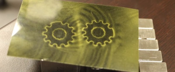
We told you about these “printable” magnets a while back. When you have the ability to squeeze many smaller magnets into a tiny spot and adjust their north/south orientations at will, you can not only control the strength of the overall magnetic field, you can construct new and seemingly physics-defying widgets. This article will not focus on the magnets themselves, but instead we’re going to peel away the closed source shroud that hides the inner workings of that nifty little printer of theirs. There has been a lot of talk about these printable magnets, but very little about how they’re made. This changes today. We’ll show you how this magnetic field printer works so you can get busy making your own.
History
Several years ago, a company called Correlated Magnetic Research introduced to the world the idea of a magnetic field printer with the Mini MagPrinter. It sold for a whopping $45,000, which limited it to businesses and well-funded universities. They eventually changed their company to Polymagnet and now focus on making the magnets themselves. It appears, however, that they’ve refined their printer for a higher resolution. Skip to 2:45 in this video to see the Mini MagPrinter in action. Now skip to 7.25 in this video to see their next generation printer. Now lets figure out how they work.
What We Know
Original Mini MagPrinter
Firstly, you can toss your Kickstarter idea in the recycle bin because they hold severalpatentsfortheirprinter. But that doesn’t mean you can’t make one in your garage or for your hackerspace. Their machine might have cost $45k, but we’d be willing to bet a dozen Raspberry Pi Zeros that you could make one for two orders of magnitude less. But first we need to know how it works. Let’s look at the science first.
The Curie Point
The Curie Point is a temperature where a magnet loses its magnetic field. It is theorized that magnetism arises from the spin and angular momentum of electrons. If you get them lined up correctly, you get a magnet. When you heat the metal past the Curie Point, this alignment gets all messed up and you lose the magnetic properties. And, of course, you can align the atoms back up by introducing the metal to a strong magnetic field.
Halbach Array
A Halbach array is created when smaller magnets are arranged so their magnetic fields are focused in a particular direction and cancel out in another direction. The magnets made by the magnetic field printer can be considered Halbach arrays.
How It Works
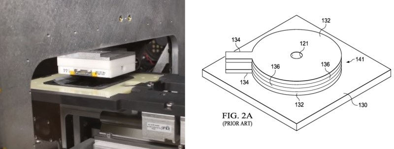
Everything begins with a blank Neodymium magnet. We’re all familiar with CNC technology, so we’ll focus on the magnetic field printing head itself. Reading through the comments of the original article, many believe that it uses a combination of heating to exceed the Curie Point and a high strength electromagnet to “write” the magnetic field into the blank. However, after looking closely at this patent, it appears this is not the case. There is no heating involved. The printer head consists of “an inductor coil having multiple layers and a hole extending through the multiple layers” and works by “emitting from the inductor coil a magnetic field that magnetizes an area on a surface of the magnetizable material…”. In short, it’s just a strong, local magnetic field.
Left – Magnetic field print head. Right – Drawing of internal structure of the print head.
Make Your Own
Now that you have a basic idea of how to print magnetic fields, you can start working on one of your own design. You already know how to make 3d printers and laser cutters. Just take one of these designs and replace the head with your custom-built magnetic printer head, whip up some software and bring this technology into the open source community. Blank Neodymium magnets and magnetic field viewing film are fairly cheap. First one to print the skull and wrenches logo gets a free t-shirt!
Fail Of The Week is a long-running series here at Hackaday. Over the years we’ve been treated to a succession of entertaining, edifying, and sometimes downright sad cock-ups from many corners of the technological and maker world.
You might think that we Hackaday writers merely document the Fails of others, laughing at others’ misfortunes like that annoying kid at school. But no, we’re just as prone to failure as anyone else, and it is only fair that we eat our own dog food and tell the world about our ignominious disasters when they happen.
And so we come to my week. I had a test process to automate for my contract customer. A few outputs to drive some relays, a few inputs from buttons and microswitches. Reach for an Arduino Uno and a prototyping shield, divide the 14 digital I/O lines on the right into 7 outputs and 7 inputs. Route 7 to 13 into a ULN2003 to drive my relays, tie 0 to 6 high with a SIL resistor pack so I can trigger them with switches to ground. Job done, and indeed this is substantially the hardware the test rig ended up using.
So off to the Arduino IDE to write my sketch. No rocket science involved, a fairly simple set of inputs, outputs, and timers. Upload it to the Arduino, and the LED on pin 13 flashes as expected. Go for a well-deserved lunch as a successful and competent engineer who can whip up a test rig in no time.
Back at the bench refreshed by the finest British pub grub, I started up the PC, plugged the shield into the Arduino, and applied the power. My sketch worked. But wait! There’s a slight bug! Back to the IDE, change a line or two and upload the sketch.
And here comes my fail. The sketch wouldn’t upload, the IDE reported a COM port error. “Damn’ Windows 10 handling of USB serial ports”, I thought, as I’m not a habitual Windows user on my own machines. Then followed something I’ve not done for quite a while; diving into the Windows control panel to chase the problem. Because it had to be a Windows problem, right?
The seasoned Arduinisti among you probably spotted my fail four paragraphs ago. We all know that pins 0 and 1 on an Arduino are shared with the serial port, but who gives it a second thought? I guess I’d always had the good fortune to drive those pins from lines which didn’t enforce a logic state, and had never ended up tying them high. Hold them to a logic 1, and the Arduino can’t do its serial thing so sketches stay firmly in the IDE.
I could have popped the shield off every time I wanted to upload a new sketch, but since in the event I didn’t need all those inputs I just lifted the links tying those pins high and shifted the other inputs up the line. And went home that evening a slightly less competent engineer whose ability to whip up a test rig in no time was a bit tarnished. Ho hum, at least the revised sketch worked and the test rig did its job exactly as it should.
Fail of the Week is a Hackaday column which celebrates failure as a learning tool. Help keep the fun rolling by writing about your own failures and sending us a link to the story — or sending in links to fail write ups you find in your Internet travels.







 The seasoned Arduinisti among you probably spotted my fail four paragraphs ago. We all know that
  Fail of the Week is a Hackaday column which celebrates failure as a learning tool. Help keep the fun rolling by writing about your own failures and