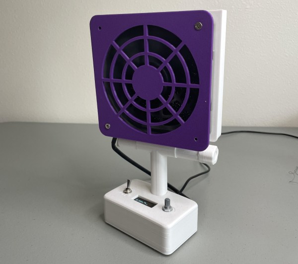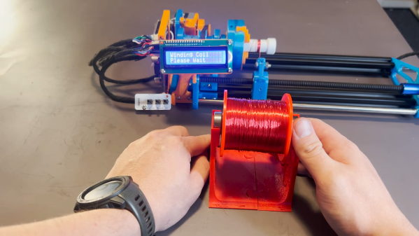
Coil winders are a popular project because doing the deed manually can be an incredibly tedious and time consuming task. After building one such rig, [Pisces Printing] wanted to find even further time savings, and thus designed an improved, faster version.
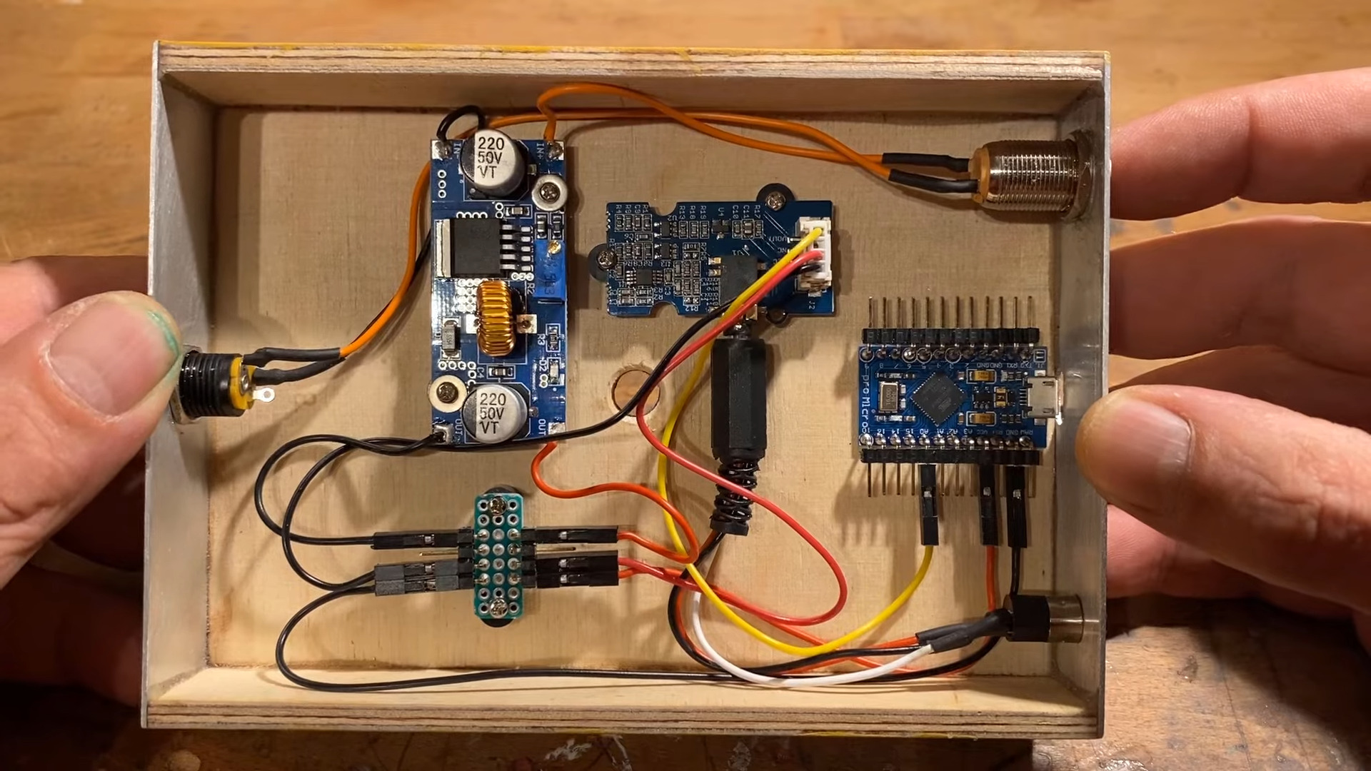
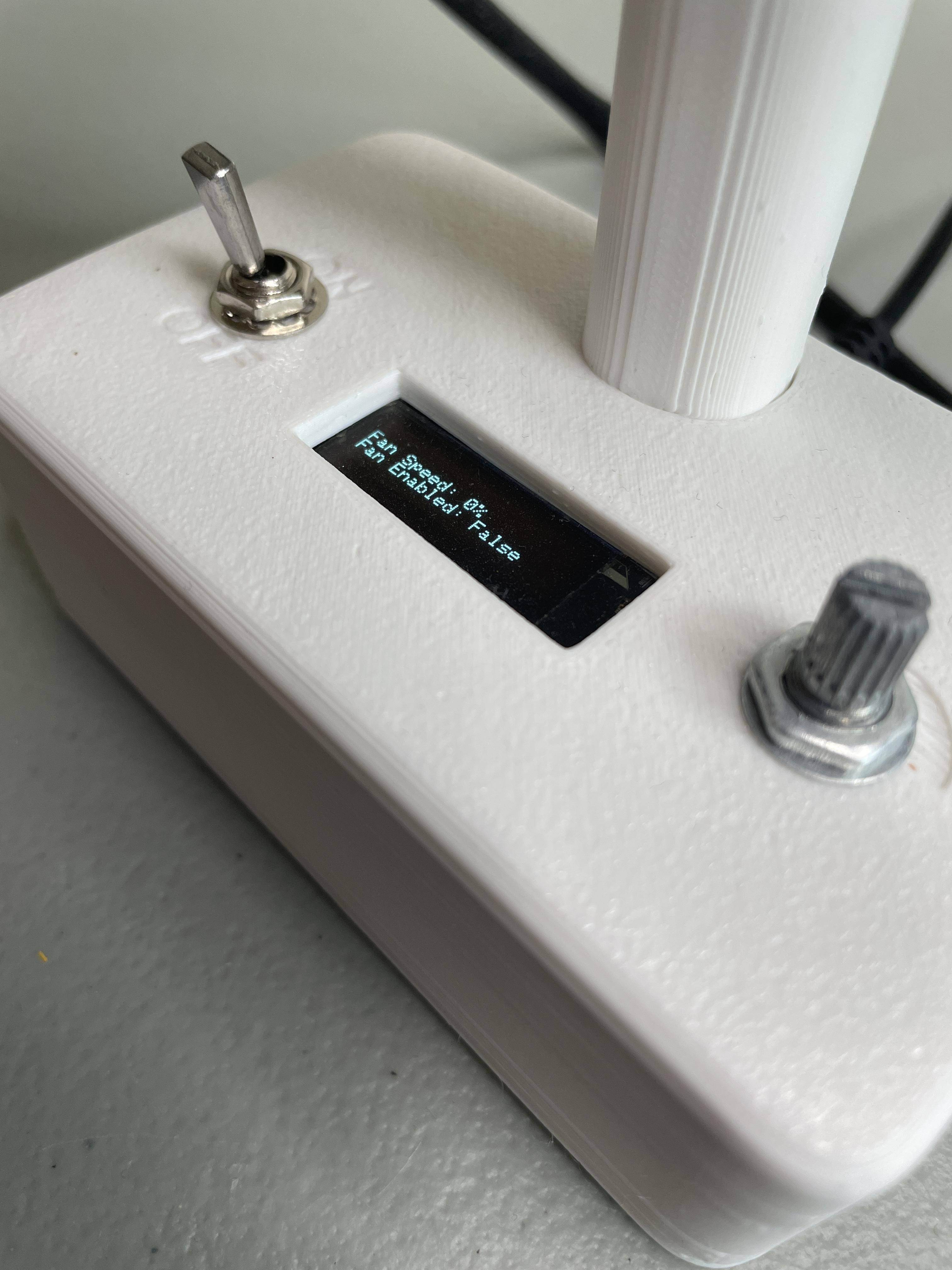
At it’s heart, it’s a straightforward design, using a linear rail and a leadscrew driven by a stepper motor. Control is via an Arduino Nano, with a few push buttons and a 16 x 2 LCD display for user feedback.
Often, completing a first build will reveal all manner of limitations and drawbacks of a design. In this case, the original winder was improved upon with faster stepper motors to cut the time it took to wind a coil. A redesigned PCB also specified a better buck converter power supply to avoid overheating issues of the initial design. A three-jaw lathe-style chuck was also 3D printed for the build to allow easy fixing of a coil bobbin.
Designing custom tools can be highly satisfying in and of itself, beyond the productivity gains they offer. Video after the break.