Rolling Foam Cutter Gives Mattress A Close Shave

There’s many different reasons why somebody might have to hack together their own solution to a problem. It could be to save money, or to save time. Occasionally it’s because the problem is unique enough that there might not be an accepted solution, so you’re on your own to create one. We think the situation that [Raph] recently found himself in was a combination of several of these aspects, which makes his success all the sweeter.

The problem? [Raph] had a pair of foam mattresses from his camper van that needed to be made thinner — each of the three inch (7.62 cm) pieces of foam needed to have one inch (2.5 cm) shaved off as neatly and evenly as possible. Trying to pull that off over the length of a mattress with any kind of manual tools was obviously a no-go, so he built a low-rider foam cutter.
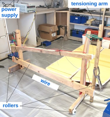
With the mattresses laying on the ground, the idea was to have the cutter simply roll across them. The cutter uses a 45″ (115 cm) long 14 AWG nichrome wire that’s held in tension with a tension arm and bungee cords, which is juiced up with a Volteq HY2050EX 50 V 20 A variable DC power supply. [Raph] determined the current experimentally: the wire failed at 20 A, and cutting speed was too low at 12 A. In the end, 15 A seemed to be the sweet spot.

The actual cutting process was quite slow, with [Raph] finding that the best he could do was about 1/8″ (3 mm) per second on the wider of the two mattresses. While the result was a nice flat cut, he does note that at some point the mattresses started to blister, especially when the current was turned up high. We imagine this won’t be a big deal for a mattress though, as you can simply put that side on the bottom.

In the end, the real problem was the smell. As [Raph] later discovered, polyurethane foam is usually cut mechanically, as cutting it with a hot wire gives off nasty fumes. Luckily he had plenty of ventilation when he was making his cuts, but he notes that the mattresses themselves still have a stink to them a couple days later. Hopefully they’ll finish outgassing before his next camping trip.

As you can imagine, we’ve covered a great number of DIY foam cutters over the years, ranging from the very simple to computerized marvels. But even so, there’s something about the project-specific nature of this cutter that we find charming.

“Unnecessary” Automation Of A DIY Star Lamp Build

It all started with a gift idea: a star-field lamp in the form of a concrete sphere with lightpipes poking out where the stars are, lit up from the inside by LEDs. When you’re making one of these, maybe-just-maybe you’d be willing to drill a thousand holes and fit a thousand little plastic rods, but by the time you’re making a second, it’s time to build a machine to do the work for you.

So maybe we quibble with the channel name “Unnecessary Automation,” but we won’t quibble with the results. It’s a machine that orients a sphere, drills the hole, inserts the plastic wire, glues it together with a UV-curing glue, and then trims the end off. And if you like crazy machines, it’s a beauty.

The video goes through all of the design thoughts in detail, but it’s when it comes time to build the machine that the extra-clever bits emerge. For instance, [UA] used a custom 3D-printed peristaltic pump to push the glue out. Taking the disadvantage of peristaltic pumps – that they pulse – as an advantage, a custom housing was designed that dispensed the right amount between the rollers. The rolling glue dispenser mechanism tips up and back to prevent drips.

There are tons of other project-specific hacks here, from the form on the inside of the sphere that simplifies optic bundling and routing to the clever use of a razor blade as a spring. Give it a watch if you find yourself designing your own wacky machines. We think Rube Goldberg would approve. Check out this video for a more software-orientated take on fiber-optic displays.

Continue reading ““Unnecessary” Automation Of A DIY Star Lamp Build”

Building The Simplest Atomic Force Microscope

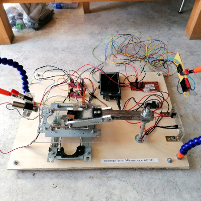
Doing it yourself may not get you the most precise lab equipment in the world, but it gets you a hands-on appreciation of the techniques that just can’t be beat. Today’s example of this adage: [Stoppi] built an atomic force microscope out of mostly junk parts and got pretty good results, considering. (Original is in German; read it translated here.)

The traditional AFM setup uses a piezo micromotor to raise and lower the sample into a very, very fine point. When this point deflects, it reads the height from the piezo setup and a motor stage moves on to the next point. Resolution is essentially limited by how fine a point you can make and how precisely you can read from the motion stages. Here, [stoppi]’s motion stage follows the traditional hacker avenue of twin DVD sleds, but instead of a piezo motor, he bounces a laser off of a mirror on top of the point and reads the deflection with a line sensor. It’s a clever and much simpler solution.

A lot of the learnings here are in the machine build. Custom nichrome and tungsten tips are abandoned in favor of a presumably steel compass tip. The first-draft spring ended up wobbling in the X and Y directions, rather than just moving in the desired Z, so that mechanism got reinforced with aluminum blocks. And finally, the line sensors were easily swamped by the laser’s brightness, so neutral density filters were added to the project.

The result? A nice side effect of the laser-bouncing-off-of-mirror setup is that the minimum resolvable height can be increased simply by moving the line sensors further and further away from the sample, multiplying the deflection by the baseline. Across his kitchen, [stoppi] is easily able to resolve the 35-um height of a PCB’s copper pour. Not bad for junk bin parts, a point from a crafts store, and a line sensor.

If you want to know how far you can push a home AFM microscope project, check out [Dan Berard]’s absolutely classic hack. And once you have microscope images of every individual atom in the house, you’ll, of course, want to print them out.

Card Radios Remembered

We know how [Techmoan] feels. In the 1980s we had a bewildering array of oddball gadgets and exciting new tech. But as kids we didn’t have money to buy a lot of what we saw. But he had a £5 note burning a hole in his pocket from Christmas and found a Casio RD-10 “card radio” on sale and grabbed it. He’s long-ago lost that one, but he was able to find a new old stock one and shows us the little gadget in the video below.

The card-thin (1.9 mm) FM radio had many odd features, especially for the 1980s. For one thing, it took a coin cell, which was exotic in those days. The headphones had a special flat connector that reminded us of an automotive fuse. Even the idea of an earbud was odd at that time.

Continue reading “Card Radios Remembered”

Building A Handheld Pong Game

Pong was one of the first video games to really enter the public consciousness. While it hasn’t had the staying power of franchises like Zelda or Call of Duty, it nonetheless still resonates with gamers today. That includes [Arnov Sharma], who put together this neat handheld version using modern components.

An ESP32 development board serves as the brains of the operation. Capable of operating at many hundreds of megahertz, it has an excessive amount of power for an application as simple as this. Nonetheless, it’s cheap, and it gets the job done. It’s paired with an SSD1306 OLED screen of 124 x 32 resolution. That might not sound like much, but it’s plenty when you’re just drawing two paddles and a ball bouncing between them. Control is via a pair of SMD push buttons for a nice responsive feel.

What’s really neat, though, is the presentation. [Arnov] wrapped the electronics in a neat bean-shaped housing that vaguely apes game controllers of the 16-bit era. Indeed, [Arnov] explains that it was inspired by the Sega Genesis specifically. It looks great with the black PCBs integrated so nicely with the bright orange 3D printed components, and looks quite comfortable to use, too.

It might be a simple project, but it’s done rather well. Just by thinking about color choices and how to assemble the base components, [Arnov] was able to create an attractive and functional game that’s a lot more eye catching than some random boards thrown in an old project box. Indeed, we’ve featured stories on advanced FR4/PCB construction techniques before, too. Meanwhile, if you’re creating your own projects with similar techniques, don’t hesitate to let us know!

Reviving A Maplin 4600 DIY Synthesizer From The 1970s

A piece of musical history is the Maplin 4600, a DIY electronic music synthesizer from the 1970s. The design was published in an Australian electronics magazine and sold as a DIY kit, and [LOOK MUM NO COMPUTER] got his hands on an original Maplin 4600 that he refurbishes and puts through its paces.

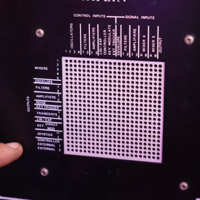
Inserting conductive pegs is how the operator connects different inputs and outputs.

The Maplin 4600 is a (mostly) analog device with a slightly intimidating-looking layout. It features multiple oscillators, mixers, envelope generators, filters, and a complex-looking patch bay on the right hand side that is reminiscent of a breadboard. By inserting conductive pins, one can make connections between various inputs and outputs.

Internally the different features and circuits are mostly unconnected from one another by default, so the patch board is how the instrument is “programmed” and the connections made can be quite complex. The 4600 is one of a few synthesizer designs by [Trevor Marshall], who has some additional details about on his website.

The video (embedded below) is a complete walk-through of the unit, including its history, quirks, and design features. If you’d like to skip directly to a hands-on demonstrating how it works, that begins around the 10:15 mark.

Synthesizers have a rich DIY history and it’s fascinating to see an in-depth look at this one. And hey, if you like your synths complex and intimidating, do yourself a favor and check out the Starship One.

Continue reading “Reviving A Maplin 4600 DIY Synthesizer From The 1970s”

Probably The Simplest Sequencing Synth

With inexpensive microntrollers capable of the most impressive feats of sound synthesis, it’s not so often we see projects that return to an earlier style of electronic music project. The 1-bit synth from [Electroagenda] takes us firmly into that territory, employing that most trusty of circuits, a 555.

It’s a time-honored circuit, a 555 provides a note clock that drives a 4017 that functions as a sequencer. This switches in a set of voltage dividers, which in turn control another 555 oscillator that produces the notes. It’s a fun toy straight from the 1970s, right down to the protoboard and hookup wire construction. There’s a demo video with some lovely beeps below, and we think most of you should have what it takes to make your own.

If you’re seeking more inspiration, may we introduce you to our Logic Noise series?

Continue reading “Probably The Simplest Sequencing Synth”