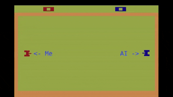
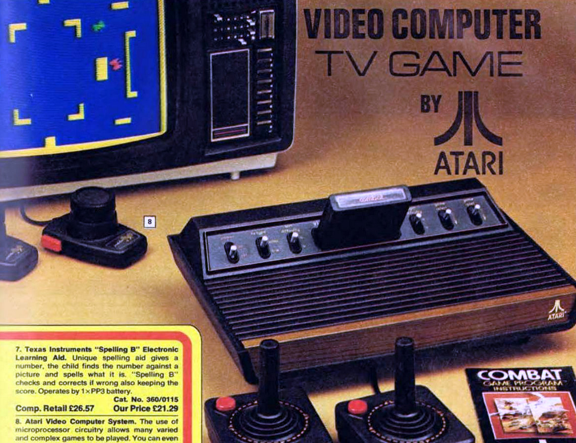
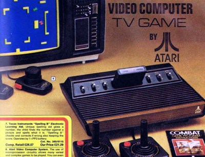
A Simple Linear Power Supply, Done Well

When reaching for a power supply design it’s normal here in 2022 to reach for a switching design. They’re lightweight, very efficient, and often available off-the-shelf at reasonable prices. Their benefits are such that it’s become surprisingly rare to see a traditional linear power supply with a mains-frequency transformer and rectifier circuit, so [ElectroBoy]’s dual voltage PSU board for audio amplifiers is worth a second look.

This type of linear power supply has an extremely simple circuit consisting of a transformer, bridge rectifier, and capacitors. The transformer isolates and steps down the AC voltage, the rectifier turns it into a rough DC, and the capacitors filter the DC to remove as much AC ripple as possible. In an audio power supply the capacitors have the dual role of filtering and providing an impulse reservoir for the supply in the event of a peak in demand imposed by the music being played. Careful selection is vital, with in this case a toroidal mains transformer and good quality capacitors being chosen.

The choice between a linear power supply such as this one and a switching design for high quality audio is by no means clear-cut, and may be something we’ll consider in our Know Audio series. The desirable properties are low noise and that impulse reservoir we mentioned, and it’s probably fair to say that while both types of power supply can satisfy them. With the extra expense of a toroidal transformer a linear supply is unlikely to be the cheaper of the two, but we suspect the balance tips in its favour due to a good linear supply being the easier to design.

Levitate The NE555 Way

Ultrasonic levitation — the practice of creating a standing wave between two ultrasonic sources and positioning lightweight objects such that they can float in the pressure minimums between them — has been a source of fascination to more than one experimenter. [Peter Lin] demonstrated this in the video below the break, by creating an ultrasonic levitation system using only the trusted chip of all true experimenters, the NE555. (Video, embedded below.)

The circuit is simplicity itself, just an astable of the type that has made a billion beepers and flashing LEDs. It drives two ultrasonic transducers in parallel, and with them pointing towards each other and a bit of gap adjustment work it can successfully levitate pieces of polystyrene. There was some work in adjusting the frequency to the transducer resonance, but that’s not a huge challenge given the right instrumentation. We can see that it would make a great demonstration of standing waves, and also a fantastic desk toy for not a lot.

We celebrate everyone’s favourite timer chip here at Hackaday, so much so that we recently ran a contest to find the best creations using it.

Continue reading “Levitate The NE555 Way”

Version 1.8 of the 80386 ISA SBC in its assembled glory. (Credit: Alexandru Groza)

Building Your Own 80386DX ISA Single Board Microcomputer

Having grown up with 386-level systems during the early 90s like so many of us, [Alexandru Groza] experienced an intense longing to experience the nostalgia of these computer systems from an interesting angle: by building his own 80386DX-based single board computer. Courtesy of the 16-bit ISA form factor, the entire system fits into a 16-bit ISA backplane which then provides power and expansion slots for further functionality beyond what is integrated on the SBMC card.

Having started the project in 2019, it is now in the home stretch towards completion. Featuring an 80386DX and 80387DX FPU alongside 128 kB of cache and a grand total of 32 MB of RAM, an OPTi chipset was used to connect with the rest of the system alongside the standard 8042-class PS/2 keyboard and mouse controller. A large part of the fun of assembling such a system is that while the parts themselves are easy enough to obtain, finding datasheets is hard to impossible for some components.

Undeterred, some reverse-engineering of signaling on functional mainboards was sufficient to fill in the missing details. Helpfully, [Alexandru] provides the full schematics and BOM of the resulting board and takes us along with bootstrapping the system after obtaining the PCBs and components. After an initial facepalm moment due to an incorrectly inserted (and subsequently very dead) CPU and boot issues, ultimately [Alexandru] gave up on the v1.6 revision of the board

Fortunately the v1.8 revision with a logic analyzer led to a number of discoveries that has led to the system mostly working, minus what appears to be DMA-related issues. Even so, it is a remarkable achievement that demonstrates the complexity of these old systems.

A miniature Vectrex console being used

Finally, The Venerable Vectrex Gets A Mini Makeover

It appears that every great console is bound to get a miniature remake: we’ve had the PlayStation Classic, the Mini NES and SNES, and even a miniature Sega Genesis/Mega Drive. But one great console that was sorely missing from that list, at least according to [Brendan], was the Vectrex. So he went ahead and built a fully-functioning miniature Vectrex Console.

If the name “Vectrex” doesn’t ring a bell in your mind, you’re not alone: a commercial failure, it was quickly forgotten by most following the 1983 video game crash. But it has retained a cult status among enthusiasts due to its unique design featuring a monochrome vector monitor, onto which you can place transparent overlays to obtain a sort-of color display. Its games can now all be emulated using software like RetroPie, which is what [Brendan] chose to run on a Raspberry Pi Model 2 that he had lying around.

As for the display, he settled on a Pi-compatible 3.5″ TFT device. Hooking it up to the Pi was easy enough, but getting the image rendered in its proper portrait orientation was quite a headache, requiring endless fiddling with drivers and configuration files.

Once he got this working, [Brendan] set to work designing a miniature copy of the Vectrex’s original case. It took a few iterations and several 10-hour runs on his 3D printer before he ended up with a sturdy case that securely held the Pi and its display in place. A few more hours of printing later he also had a handheld controller, which he based on an Arduino Pro Mega. The Arduino reads out four regular pushbuttons and a joystick, and communicates with the Pi through a coiled USB cable.

The end result, as you can see in the video embedded below, is the cutest little Vectrex we’ve ever seen. It’s really the opposite of this big-screen Vectrex project. We’ve also seen a Vectrex projector, and even one with a real color monitor hacked in. Continue reading “Finally, The Venerable Vectrex Gets A Mini Makeover”

A Timex Datalink smartwatch next to an Arduino

Arduino Keeps Your Classic Timex Datalink In Sync

The Timex Datalink was arguably the first usable smartwatch, and was worn by NASA astronauts as well as geek icons like Bill Gates. It could store alarms, reminders and phone numbers, and of course tell the time across a few dozen time zones. One of the Datalink’s main innovations was its ability to download information from your PC — either through flashing images on a CRT monitor or through a special adapter plugged into a serial port.

With CRTs thin on the ground and original serial adapters fetching ludicrous prices online, classic Datalink users today may find it hard to keep their watches in sync with their Outlook calendars. Fortunately for them, [famiclone] came up with a solution: a DIY Datalink adapter based on an Arduino. It works the same way as Timex’s serial adapter, in that it receives data through the computer’s serial port and transmits it to the watch by flashing a red LED.

Updating your watch does require the use of the original Datalink PC software, which only runs on classic operating systems like Windows 95 or 98, so you’ll need to keep a copy of such an OS running. Luckily, it has no problem with virtual machines or USB COM ports, so at least you don’t need to keep vintage PC hardware around. Then again, whipping out a 1995 Pentium laptop to update your Timex watch would make for the ultimate geek party piece.

Love classic geeky watches? Check out this featured article we did on them a few years ago. If you’re interested in using computer monitors to transmit data optically, we’ve covered a few projects that do just that.

Polar Planimeter Quantifies Area By Plotting Perimeter

These days it’s hard to be carry the label “maker” or “hacker” without also being proficient in some kind of CAD- even if the C is for Cardboard. But before there was CAD there was Drafting and its associated arts, and one couldn’t just select a shape and see its area in the square unit of your choice. So how could an old school draftsman figure out the area of complex shapes? [Chris Staecker] introduces us to the polar planimeter, a measuring tool created specifically for the purpose and explained in full in the video below the break.

The polar planimeter being discussed is a higher end unit from the 1960’s. Interestingly, the first polar planimeters were invented in the early 19th century even before the math that describes their function was completed. A lever is placed in a fixed position on one end and into the planimeter on the other. The planimeter itself has another arm with a reticle on it. The unit is zero’d out with a button, and the outline of the shape in question is traced in a clockwise fashion with the reticle.

What makes the polar planimeter capable of measuring in multiple dimensions is the fixed arm. The fixed arm pivots around, allowing the planimeter to track angle changes which affects the output. So, the planimeter isn’t just measuring the length of the perimeter, but the size of the perimeter. The final measurement is output in square inches.

Overall it’s a really slick tool we didn’t know existed, and it’s fascinating to see how such problems were solved before everything could be done with a mouse click or two. Be sure to check out this 100+ year old reference set to round out your knowledge of past knowledge. Thanks to [Zane] for the great tip!

Continue reading “Polar Planimeter Quantifies Area By Plotting Perimeter”

Brick And Motor Table Saw Delivers Paper Cuts On Demand

Twenty Two Motors. Fifty gears. Eighty Two Hundred RPM. Hundreds of individual pieces, and one sheet of glossy paper cut into a disk. This isn’t a nightmare driven Rube Goldberg machine. Instead, it’s a Lego monstrosity created by [GazR] of [GazR’s Extreme Brick Machines!], and all of these parts are flying in formation for one Lego slicing purpose. In the video below the break, you can see what very well may be the worlds most powerful Lego and Paper table saw.

Starting out with a build that had a mere fourteen motors in a platform that looked quite a lot more like a table saw, [GazR] learned that having only fourteen motors turning a Lego based blade was not a good combination. In the next iteration, the same number of motors were used, but the gearing was increased to bring RPM up, and a Lego toy saw blade took care of cutting duties.

Seeing that higher speeds with thinner blades was a winning trend, [GazR] stepped it up to the aforementioned 8200 RPM twenty-two motored paper whirling Lego Death Machine. Yes, [GazR] cut Lego, carrots, carpet, and paper- all with circular sheet of paper.

Do Lego mechanisms turn your gears? You might enjoy this Legopunk Orrery from the Hackaday archives, too. Thanks to [Keith] for the great tip. Be sure to submit your own tips via the Hackaday Tips Line, or the #Submit-A-Tip channel in the Hackaday Discord server.

Continue reading “Brick And Motor Table Saw Delivers Paper Cuts On Demand”