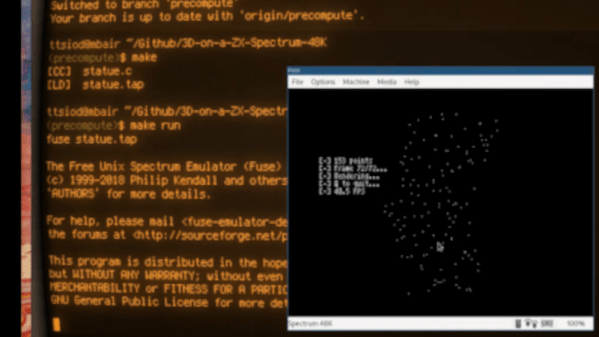
These Bit Twiddling Tricks Will Make Your Coworkers Hate You

In the embedded world, twiddling a few bits is expected behavior. Firmware is far enough down the stack that the author may care about the number of bits and bytes used, or needs to work with registers directly to make the machine dance. Usually these operations are confined to the typical shifting and masking but sometimes a problem calls for more exotic solutions. If you need to descend down these dark depths you invariably come across the classic Bit Twiddling Hacks collected by [Sean Eron Anderson]. Here be dragons.

Discussions of bit math are great opportunities to revisit Wikipedia’s superb illustrations

Bit Twiddling Hacks is exactly as described; a page full of snippets and suggestions for how to perform all manner of bit math in convenient or efficient ways. To our surprise upon reading the disclaimer at the top of the page, [Sean] observes that so many people have used the contents of the page that it’s effectively all been thoroughly tested. Considering how esoteric some of the snippets are we’d love to know how the darkest corners found use.

The page contains a variety of nifty tricks. Interview content like counting set bits makes an early appearance.  There’s more esoteric content like this trick for interleaving the bits in two u16’s into a single u32, or rounding up to the next power of two by casting floats. This author has only been forced to turn to Bit Twiddling Hacks on one occasion: to sign extend the output from an unfortunately designed sensor with unusual length registers.

Next time you need to perform an operation with bitmatch, check out Bit Twiddling Hacks. Have you ever needed it in production? How did you use it? We’d love to hear about it in the comments.

The Flexible Permanence Of Copper Tape Circuits

Somewhere between shoving components into a breadboard temporarily and committing them to a piece of protoboard or a PCB lies the copper tape method. This flexible Manhattan-style method of circuitry formed the basis for [Bunnie Huang]’s Chibitronics startup, and has since inspired many to stop etching boards and start fetching hoards of copper tape.

[Hales] hit the ground running when he learned about this method, and has made many a copper tape circuit in the last year or so. He offers several nice tips on his site that speak from experience with this method, and he’ll even show you how to easily work an SMD breakout board into the mix.

Generally speaking, [Hales] prefers plywood as the substrate to paper or cardboard for durability. He starts by drawing out the circuit and planning where all the tape traces will go and how wide they need to be. Then he lays out copper traces and pads, rubs the tape against the substrate to make it adhere strongly, and reinforces joints and laps with solder before adding the components. As you can see, copper tape circuits can get pretty complicated if you use Kapton tape as insulation between stacked layers of traces.

Copper and Kapton (polyimide) tape are just two of the many useful tapes you may not be aware of. Stick with us a moment and check out [Nava Whiteford]’s exploration of various adhesive marvels.

Camcorder Viewfinder Converted To Diminutive Vector Display

We generally cast a skeptical eye at projects that claim some kind of superlative. If you go on about the “World’s Smallest” widget, the chances are pretty good that someone will point to a yet smaller version of the same thing. But in the case of what’s touted as “The world’s smallest vector monitor”, we’re willing to take that chance.

If you’ve seen any of [Arcade Jason]’s projects before, you’ll no doubt have noticed his abiding affection for vector displays. We’re OK with that; after all, many of the best machines from the Golden Age of arcade games such as Asteroids and Tempest were based on vector graphics. None so small as the current work, though, based as it is on the CRT from an old camcorder’s viewfinder. The tube appears to be about 3/4″ (19 mm) in diameter, and while it still had some of its original circuitry, the deflection coils had to be removed. In their place, [Jason] used a ferrite toroid with two windings, one for vertical and one for horizontal. Those were driven directly by a two-channel push-pull audio amplifier to make patterns on the screen. Skip to 15:30 in the video below to see the display playing [Jerobeam Fenderson]’s “Oscilloscope Music”.

As much as we’d love to see a tiny game of Battlezone played on the diminutive display, there’s only so much it can do. Maybe an analog version of this adorable digital oscilloscope would be possible?

Continue reading “Camcorder Viewfinder Converted To Diminutive Vector Display”

Poking Around Inside A Pair Of Classic Gaming Gifts

Retro gaming is huge right now, and like probably millions of other people, [wrongbaud] found himself taking possession of a couple faux-classic gaming gadgets over the holidays. But unlike most people, who are now using said devices to replay games from their youth, he decided to tear into his new toys to see how they work.

The first to get pulled apart is a handheld The Oregon Trail game, which Hackaday readers may recall from a teardown we did back when it was first released. His work continues right where our teardown left off, by pulling the game’s two EEPROM chips out and dumping their contents. As expected, [wrongbaud] found that the I2C connected chip contained the game save information, and the SPI flash chip stored the actual game files.

Next up was an HDMI “stick” from Bandai Namco that allows the user to play a selection of NES games. Here again [wrongbaud] liberates the flash chip and dumps it for examination, this time using an ESP32 tool of his own creation. Inside the firmware image he’s able to identify several elements with the help of binwalk, such as splash screen graphics and text strings.

But perhaps most interestingly, he found that binwalk was able to automatically extract the NES ROMs themselves. After verifying they were standard ROMs with an NES emulator, he theorizes that repacking the firmware with different ROMs should be possible should anyone feel so inclined.

Both of these hacks are fantastic examples of how you can reverse engineer a device’s firmware with low cost hardware, open source tools, and a healthy dose of patience. Even if you aren’t interested in fiddling with The Oregon Trail or swapping out the Mappy ROM for Contra, this write-up is an invaluable resource for anyone looking to do their own firmware analysis.

This isn’t the first time [wrongbaud] has hacked around inside these extremely popular retro games, either. Just last month we covered some of his previous exploits with the re-released versions of Rampage and Mortal Kombat.

Magnetic Circuits Are More Attractive Than Breadboarding

Let’s face it, breadboarding can be frustrating, even for advanced electronics wizards. If you have an older board, you could be dealing with loose tie points left from large component legs, and power rails of questionable continuity. Conversely, it can be hard to jam just-made jumper wires into new boards without crumpling the copper. And no matter what the condition of the board is, once you’ve plugged in more than a few components, the circuit becomes hard to follow, much less troubleshoot when things go pear-shaped.

In the last twenty years or so, we’ve seen systems like Snap Circuits and Little Bits emerge that simplify the circuit building process by making the connections more intuitive and LEGO-like than even those 160-in-1 kits where you shove component legs between the coils of tight little springs. You will pay handsomely for this connective convenience. But why should you? Just make your own circuit blocks with cardboard, magnets, and copper tape. It should only cost about 10¢ each, as long as you source your magnets cheaply.

[rgco] gives the lowdown on building a minimal set of 23 component and connector blocks using 100 magnets. He’s got 11 example circuits to get you started, and some example videos of more advanced circuits that got tacked up after the break.

This method of making the circuit look more like the schematic may be the best way for the visually-inclined to learn electronics. But the best way to learn electronics depends on where you’re coming from.

Continue reading “Magnetic Circuits Are More Attractive Than Breadboarding”

Focus Stacking For Tiny Subjects

Focus stacking is a photographic technique in which multiple exposures are taken of a subject, with the focus distance set to different lengths. These images are then composited together to create a final image with a greater depth of field than is possible with a single exposure. [Peter Lin] built a rig for accurate focus stacking with very small subjects.

The heart of the rig is a motion platform consisting of a tiny stepper motor fitted with a linear slide screw. This is connected to an Arduino or PIC with a basic stepper driver board. While the motor does not respond well to microstepping or other advanced techniques, simply driving it properly can give a resolution of 15 μm per step.

The motor/slide combination is not particularly powerful, and thus cannot readily be used to move the camera or optics. Instead, the rig is designed for photography of very small objects, in which the rail will move the subject itself.

It’s a tidy build that would serve well for anyone regularly doing macro focus stack photography. If you’ve been trying to better photograph your insect collection, this one is for you. It’s a valuable technique and one that applies to microscopy too. Video after the break.

Continue reading “Focus Stacking For Tiny Subjects”

A VFD Wall Thermometer

Want to build something using VFD tubes, but don’t need yet another clock project? In that case, this wall mounted temperature and humidity display created by [commanderkull] might be exactly what you’re looking for. With six IV-11 tubes, this display is a practical way to add some of that gorgeous blue-green glow to your home or office.

The USB powered display uses a XL6009 and an XL7015 to provide the 24 V and 1.8 V needed by the IV-11 tubes, respectively. Both of which can be disconnected with jumpers to shut down the tubes without powering off the entire device, a useful feature when programming and debugging the display’s ATmega328P microcontroller. Each tube is connected to the ATmega with an 74HC595 shift register and a UDN2981 driver. Temperature and humidity data is provided, perhaps unsurprisingly, by the exceptionally common DHT22 sensor.

If you are looking to build another clock with these style tubes, there’s certainly enough prior art out there to get you started. We’ve also seen faux VFDs that you could use for either project, just in case you aren’t looking to deal with the voltage requirements and relative rarity of the real thing.