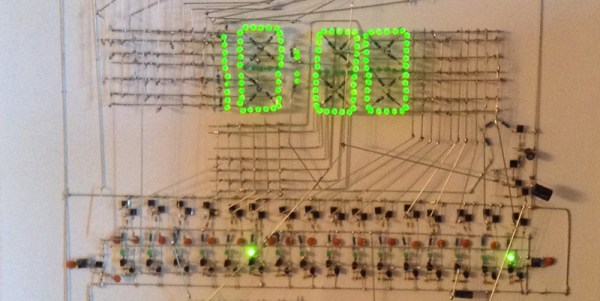
[Kevin Rye] built a discrete TTL based seven-segment clock, and he wasn’t too happy with the ugly insides compared to the nice enclosure he built for it. He embarked on creating another large seven-segment clock to put inside that enclosure.
Clocks, and specifically seven-segment based ones, aren’t anything new to write about. This particular project, which is still work in progress, is interesting. [Kevin] is an experienced hacker, but the problems he encountered and resolved along the way could prove useful to a fellow hacker someday.
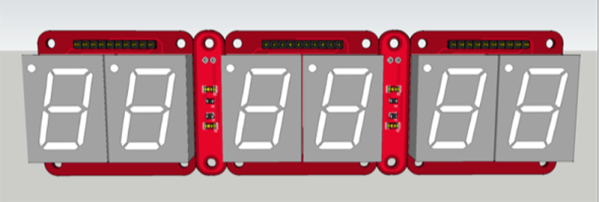
To start with, he tried rectifying his old build. But in his own words “You can polish a turd, but it’s still a turd.” Five years later, he’d had enough. He’s built a lot of other clocks, but rather than repurposing them, he decided to start from scratch. He quickly breadboarded an Arduino, some displays and drove them using the Multiplex7seg library. That library supports only four characters, so he was back to the drawing board. With a fresh start, his design is now moving along nicely. For now, he’s designed three boards for the display, two boards for the colons between digits, the main Arduino-clone controller board and a 3D printed front frame to hold the displays. It will be nice to finally see that enclosure receive some fitting occupants and bring this build to closure.