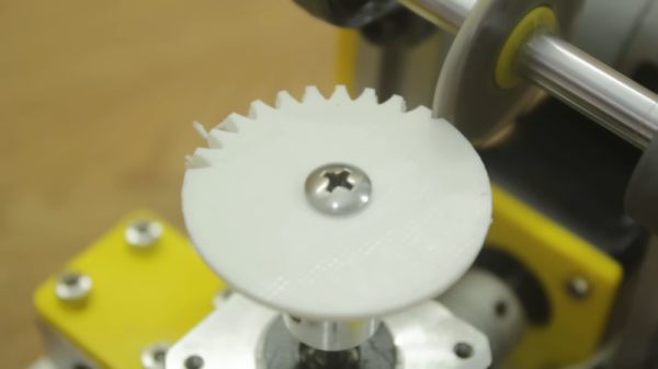
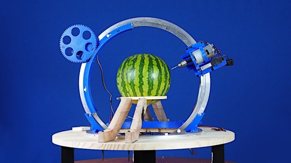
Wire EDM

Bringing The Power Of EDM To The Home Shop

When you see something made from metal that seems like it would be impossible to manufacture, chances are good it was made with some variety of electrical discharge machining. EDM is the method of choice for hard-to-machine metals, high aspect ratio hole drilling, and precise surface finishes that let mating parts slip together with almost zero clearance. The trouble is, EDM is a bit fussy, and as a result hasn’t made many inroads to the home shop.

[Action BOX] aims to change that with a DIY wire EDM machine. In wire EDM, a fine brass wire is used as an electrode to slowly erode metal in a dielectric bath. The wire is consumable, and has to constantly move from a supply spool through the workpiece and onto a takeup spool. Most of the build shown in the video below is concerned with the wire-handling mechanism, which is prototyped from 3D-printed parts and a heck of a lot of rollers and bearings. Maintaining the proper tension on the wire is critical, so a servo-controlled brake is fitted to the drivetrain, which itself is powered by a closed-loop stepper. Tension is measured by a pair of strain gauges and Arduinos, which control the position of the shaft brake servo and the speed of the motor on the takeup spool.

Unfortunately, in testing this setup proved to live up to EDM’s fussy reputation. The brass wire kept breaking as soon as cutting started, and [Action BOX] never made any actual cuts. There’s certainly promise, though, and we’re looking forward to developments. For more on EDM theory, check out [Ben Krasnow]’s look at EDM hole-drilling.

Continue reading “Bringing The Power Of EDM To The Home Shop”

An OpenSCAD Library For All Your CNC Cutting Needs

While there’s always the edge case, there’s a strong likelihood that if you’re using OpenSCAD, you’re probably working on a CAD model that you intend to 3D print at some point. Of course that’s not to say this is all you can do in OpenSCAD, but it’s arguably what it does best. If you wanted to make artistic models, or maybe render what your new kitchen will look like, there are other tools better suited to such tasks.

But thanks to lasercut.scad, a library that [Brendan Sleight] has been working on for the last several years, we might have to reconsider our preconceived dimensional notions. Instead of designing parts for 3D printing, his library is all about creating parts intended for subtractive manufacturing. Originally (as the name implies) it was geared towards laser cutting, but the project has since evolved to support CNC routers, vinyl cutters, and pretty much anything else that can follow a DXF file.

This “clip” joint is great for acrylic.

The library has functions for creating the standard tricks used to build things from laser-cut pieces, like finger joints, captive nuts, and assembly tabs. If it was something you once saw holding together an old wooden 3D printer kit back in the day, you can probably recreate it with lasercut.scad. It even supports a pretty wild piece of rotational joinery, courtesy of [Martin Raynsford].

Don’t have a way of concentrating a sufficient number of angry photons at your workpiece? No worries. The library has since been adapted to take into account a parametric kerf width, which lets you dial in how much of a bite your particular tool will take from the material when it does the business. There are even special functions for dealing with very thin cuts, which [Brendan] demonstrates by assembling a box from sheet vinyl.

Of course, those who’ve used OpenSCAD will know there’s not an “Export for CNC” button anywhere in the stock interface. So to actually take your design and produce a file your cutter can understand, [Brendan] has included a Bash script that will run the necessary OpenSCAD incantations to produce a 2D DXF file.

[Brendan] decided to send this one in after he saw the aluminum enclosure OpenSCAD library we covered recently. If you’ve got your own pet project that bends some piece of hardware or software to your will, don’t be shy to let us know.

Mini Linear Actuators From DVD Drive Parts

For many years now a source for some of the smallest and cheapest home made CNC mechanisms has been the seemingly never-ending supply of surplus CD and DVD-ROM drives. The linear actuator that moves the laser may not be the longest or the strongest, but it’s free, and we’ve seen plenty of little X-Y tables using CD drives. It’s these mechanisms that [Nemo404] has taken a little further, freeing the lead screw and motor from the drive chassis and placing them in a 3D-printed enclosure for a complete linear actuator that can be used in other projects. (Video, embedded below.)

There seems to be no positional feedback, not even the limit switch that would grace a typical CD drive, but aside from that it makes for a compact unit. There are two versions, one for a linear bearing and the other for the brass bushes found in CD drives. It’s unclear how strong the result is, but it appears to be strong enough to demonstrate lifting a small container of screws.

Should you need to make your own actuator then aside from the easy-to-obtain old CD drive the files can be found on Thingiverse. And introduce yourself to the world of CD drives for CNC machines by taking a look at this mill.

Thanks [BaldPower] for the tip!

Continue reading “Mini Linear Actuators From DVD Drive Parts”

A Nested Gear Clock

One of the most common projects we see here at Hackaday is a clock. It could just be that we as humans are fascinated by the concept of time or that making a piece of functional art appeals to our utilitarian sense. In that spirit, [Alexandre Chappel] set out to make a large mechanical clock with complex gears.

The initial design was made in Fusion360 over a week and then in a somewhat bold move, [Alexandre] started up the CNC and cut all the parts out of valchromat. The basic idea of the clock is that the numbers move on the clock, not the hands. So the clock should show 10:25 instead of moving hands to the 10 and the 5. Most of the clock is made of up stacked gear assemblies, geneva drives, and many bearings. A single stepper motor drives the whole clock, which [Alexandre] admits is a bit of a cheat since trying to add springs and an escapement would add complexity to an already complex clock. He did have to adjust and recut a few gears but most of the assembly came together nicely. Some 3d printed numbers dropped into the CNCed slots offers much-improved readability.

A few problems became apparent once the system was together. The numbers don’t quite line up perfectly, which is unfortunate. He mentioned that tighter tolerances on the gears would likely help there. A fatal design flaw on the smallest disk became apparent as it needs to turn a sixth of the circle whereas the outer circle is just turning a tenth of the circle. Mechanical advantage isn’t in [Alexandre’s] favor and the stepper skips some steps and it slowly makes its way towards the next second digit of the hour.

If you’re looking for more beautiful artistic clocks, why not check out this circuit sculpture one?

Continue reading “A Nested Gear Clock”

DIY CNC Uses Lots Of 3D-Printed Parts

There are probably almost as many DIY CNC designs as there are DIY CNCs. And there’s nothing wrong with that! We really liked [maxvfischer’s] documentation on GitHub for a machine he made based on a design by [Ivan Miranada].

In addition to a complete bill of materials, there are Fusion 360 files and very good instructions. There are several tips that seemed like they would help even if you were building similar machines.

The machine uses HTD5M belts instead of the more prevalent lead screw design. Everything slides on MGN12H slides. There are detailed photographs covering not just the tricky parts but even how to extend the stepper motor wires.

The original design used a Makita RT0700C for the spindle, but [max] couldn’t find one of those, but found a similar version with the same dimensions.

The only tip we would add is to be careful using taps in a handheld drill. (Don’t ask us how we know that.) A drill press is safer, or you can even use a tap handle and do it the old-fashioned way.

The firmware is grbl on an Arduino, and there are complete instructions for setting that up, too. We were amazed at the number of pictures included along with the detailed description. If you were ever afraid you couldn’t duplicate a CNC project, this might be the one to tackle.

There are, of course, cheaper and simpler options with fewer capabilities. Some are even almost free courtesy of the local dumpster.

an image of the graffomat at work

Automate Your Graffiti With The Graffomat!

In Banksy’s book, Wall and Piece, there is a very interesting quote; “Imagine a city where graffiti wasn’t illegal, a city where everybody could draw whatever they liked…”. This sounds like it would be a very exciting city to live in, except for those of us who do not have an artistic bone in their body. Luckily, [Niklas Roy] has come up with the solution to this problem; the Graffomat, a spray can plotter.

The Graffomat is, in its creator’s own words, a “quick and dirty graffiti plotter.” It is constructed primarily from wood and driven by recycled cordless drills that pulls string pulleys to move the gantry.  The Arduino Nano at the heart of the Graffomat can be controlled by sending coordinates over serial. This allows for the connection of an SD card reader to drip-feed the machine, or a computer to enable real-time local or over-the-internet control.

We are especially impressed with how [Niklas] handled positional tracking. The cordless drills were certainly not repeatable like a stepper motor, as to allow for open-loop control. Therefore, the position of the gantry and head needed to be actively tracked. To achieve this, the axes are covered with black and white striped encoder strips, that is then read by a pair of phototransistors as the machine moves along. These can then be paired with the homing switches in the top left corner to determine absolute position.

Graffomat is not the first automated graffiti machine we’ve covered. Read here about the robot that painted murals by climbing smokestacks in Estonia. 

Continue reading “Automate Your Graffiti With The Graffomat!”

Small low-cost CNC mill with rotary tool

Minimal Mill: The Minamil

Having a few machine tools at one’s disposal is a luxury that not many of us are afforded, and often an expensive one at that. It is something that a large percentage of us may dream about, though, and with some commonly available tools and inexpensive electronics a few people have put together some very inexpensive CNC machines. The latest is the Minamil, which uses a rotary tool and straps it to an economical frame in order to get a functional CNC mill setup working.

This project boasts impressively low costs at around $15 per axis. Each axis uses readily available parts such as bearings and threaded rods that are readily installed in the mill, and for a cutting head the build is based on a Dremel-like rotary tool that has a similarly low price tag. Let’s not ignore the essentially free counterweight that is used.

For control, an Arduino with a CNC shield powers the three-axis device which is likely the bulk of the cost of this project. [Paul McClay] also points out that a lot of the material he needed for this build can be salvaged from things like old printers, so the $45 price tag is a ceiling, not a floor.

The Minamil has been demonstrated milling a wide variety of materials with excellent precision. Both acrylic and aluminum are able to be worked with this machine, but [Paul] also demonstrates it in its capacity to mill PCBs. It does have some limitations but for the price it seems that this mill can’t be beat, even compared to his previous CNC build which repurposed old CD drives.