For all the 3D printers that hit the Hackaday tip line, it’s surprising we don’t see more CNC routers. They’re arguably more useful tools, and with the ability to mill wood, plastic, and non-ferrous metals, open up the door to a whole bunch more potential builds. One of the most popular – and certainly one of the least expensive – CNC routers out there, the Shapeoko, just received a huge update that makes this minimal machine even more capable.
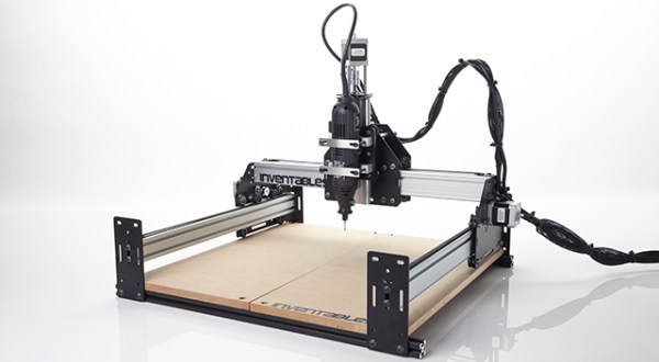
The new Shapeoko 2 keeps the same V wheel on an aluminium extrusion design with Makerslide, but fixes a few problems that limited the original Shapeoko. There’s a larger work area on this version, and the Y axes feature dual stepper motors. The biggest feature, we think, is the ability to handle materials larger than the machine itself thanks to its open front and back.
The Shapeoko 2 is available in two versions, a $300 mechanical kit that requires you to go out and get some motors, a power supply, and a grblShield, the full version, for $650, includes everything you’ll need to start routing wood metal and plastic at home.