Some of us may have been accused of living in Mom’s basement – [Benjamin] kicks it up a notch by keeping an industrial robot in his parent’s attic shed loft.
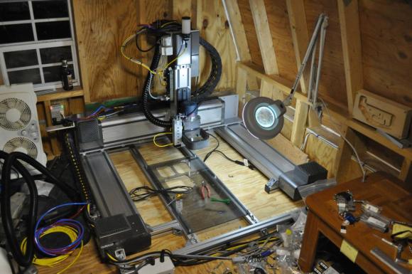
[Benjamin] was tasked with stripping down some retired equipment at work. It turns out the “retired equipment” was three Cartesian robots from Adept Robotics. These are large industrial XYZ platforms capable of high speed movements (3000 IPM rapids!).
Getting from a decommissioned machine to a working CNC is never a simple path. In this case [Ben] was able to make the transition relatively easily. Each axis of the robot has a 400 Watt Yaskawa servo with a 65k encoder and brake. The original Adept servo amps and control system was still working, so he kept it. The controllers were new enough that they communicate over a daisy chained IEEE1394 (Firewire) link. That is relatively modern compared to some of the conversions we’ve seen in the past. The final piece of the puzzle was G-code creation Translating common G-code to a format his machine could recognize. Ben chose MeshCAM for the task.
One problem [Ben] ran into was stuttering on the X-axis. The original machines only had a single sided drive system on the X-axis. Single side is fine for an assembly machine that doesn’t see any tool load. However for a CNC machine that will see spindle loads, a single side drive creates a twisting force which threatens to rack the entire frame. He used one of the drive systems from his spare robot to convert his main machine to a double-sided drive, eliminating the issue.
Continue reading “Turn A Decommissioned Robot Into A CNC Machine”