Stewart Platform Reinvents The Wheel So You Don’t Have To

StewartPlatform

[Dan Royer] has noticed that most university projects involving a Stewart platform spend more time building a platform than on the project itself. He hopes to build a standard platform universities can use as the basis for other projects.

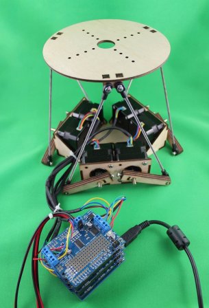
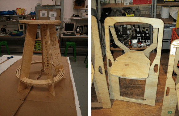
Stewart platforms are six degree of freedom platforms often seen hefting flight simulators or telescopes. The layout of the actuators allows movements in X,Y,and Z as well as pitch, roll and yaw. While large platforms often use hydraulic systems to accelerate heavy loads quickly. [Dan] is looking at a smaller scale system. His platform is built of laser cut wood and uses six steppers to control motion.

One of the harder parts in designing a platform such as this is creating a mechanical system that is strong, precise, and smooth. With so many linkages, it’s easy to see how binding joints could bring the entire thing to a grinding halt. [Dan] is currently using RC helicopter ball joints, but he’s on the lookout for something even smoother.

Continue reading “Stewart Platform Reinvents The Wheel So You Don’t Have To”

Revenge Of The Glueless Stool And A New Folding Chair

glueless stool

[Vincent] is at it again, with the final iteration of his glueless stool and a new project.

As many of you commented on the original post, three legs might not be enough. He might have taken note, as the final design contains not 3, not 4, but five legs. After the break we have a clip of it being used, and it looks quite sturdy!

But is that it? Is [Vincent] done with innovative wood furniture? Nope. Not since his wife came up with a challenge to create a practical, foldable, and especially, not ugly — chair. He began by researching the dry subject of chairs and determined the approximate popliteal height that his chair should provide. Keeping with the theme, he wanted this chair to be cut from a single piece of wood, just like the stool. A few sketches later and he had a basic design ready, still glueless, but unfortunately this time requiring hinges. After a few hiccups in his CNC program, he had a working foldable chair, but our guess is it’s not quite the final design.

Just like last time, all the files are freely available from his Github, so if you happen to have a CNC router, or maybe a laser cutter, you can make your own!

Continue reading “Revenge Of The Glueless Stool And A New Folding Chair”

Fail Of The Week: Laser Cutter That Makes Jagged Edges

This Fail of the Week is really only a failure because of the standards to which [eLabz] holds himself. The rig pictured above is a laser cutter built out of DVD drive parts. It goes above and beyond most of the optical drive CNC projects we see around here — it actually makes cuts! But [eLabz] looks on it as a failure because the steps of the driver motors are visible as jagged edges in those cuts. We see this more as a pausing point in the development process before the next refinement is made.

Continue reading “Fail Of The Week: Laser Cutter That Makes Jagged Edges”

Extruded Rail And 3D Printed Connectors Form A Proper Laser Engraver

3d-printed-laser-engraver

Fast and accurate is a good description of this laser engraver built by [Ragnar] and [Gunnar]. The’re planning to show it off at the Trondheim Maker Faire after the new year but they took it out in the wild for the PSTEREO Mini Maker Faire (also in Trondheim) this past August. The video below gives an overview of the build process and the engraver at work. But we also enjoyed reading the post about a few missteps in the early prototyping process. We call this one a proper laser engraver because it was purpose built from the ground-up. We still like seeing the engravers hacked from optical drives, but this really is a horse of a different color in comparison.

From the start they’re using familiar parts when it comes to CNC builds. The outer frame is made of extruded aluminum rail, with precision rod for the gantry to slide upon. Movement is facilitated with stepper motors and toothed belts, with all of the connecting and mounting parts fabricated on a 3D printer. The mistake made with an early (and unfortunately mostly assembled) prototype was that the Y axis was only driven on one side when it really needed to be driven on both. But filament is relatively cheap so a few tweaks to the design were able to fix this and get the production back on track.

Continue reading “Extruded Rail And 3D Printed Connectors Form A Proper Laser Engraver”

Machining An Orrery

What in the heck is an Orrery? If you’re looking at the image above we’re sure you’ve already figured it out (kudos to the big brains that knew the word). For those that don’t get it, an Orrery is a mechanical device that represents the movements of planets and moons. We never thought of building one ourselves. After seeing the machining process for what’s shown above we’re not sure if we’re excited, or scared off by all the work that went into it.

You might want to bust out the Chromecast and hit the sofa for this one. There are dozens of YouTube videos showing the build. From cutting sheet stock into round slugs, to making teeth, teeth, teeth, and more teeth it’s not just the gears that go into this one. You’re also going to needs the orbs themselves.

We have fond (perhaps scary) memories of the first time we saw an Orrery as a part of the set in The Dark Crystal.

Continue reading “Machining An Orrery”

Git With Eagle: Add Meaning to Diff

a-glimpse-of-git-with-eagle
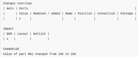
We love Git. We know everyone has their favorite version tracking tools. But even those that don’t care for Git should see the value of getting meaningful Diff data from tracking Eagle layout files.

Was that last sentence just gibberish to you? Let’s take a step back. A few years ago it was impossible to use version control with Eagle at all because the schematic and PCB layout software used to save its files as binaries. But then Cadsoft transitioned to saving Eagle files as XML. This opened the door for things like scripting to rename parts en masse and to track the files under version control. One problem with the latter has been that performing a Diff on two different versions of a file results in XML changes that are probably not human readable. [Patrick Franken] wrote this script to add at least a glimmer of meaning.

We’d love to see some kind of side-by-side highlighting on the schematic or board renderings themselves. But that’s quite a ways off if we ever actually see it. For now his script will take the Diff and print out the tables seen above denoting which types of changes were made from one version to the next. It’s a start, and we hope it inspires even more work in this area.

Scratch-built Gigapixel Scanner

scratch-built-gigapixel-scanner

The presence of a camera in this image may be a bit confusing since we’re calling it a scanner. What’s actually going on is that macro-images this piece of art are being captured automatically. The multiple shots will later be assembled into one fascinatingly high-resolution image. The CNC scanner rig is [Charlie Romer’s] summer project.

Unfortunately [Charlie] hasn’t yet collected all the information on the project into one place. After the break you’ll find more images, as well as a few demo videos. The best place to start is probably his proof-of-concept from this Spring. He shows a single-axis CNC mount for the camera. It takes an entire row of images. The assembled photo from that test is shown below. We believe the faint yellow dots in the macro part of the example are fingerprints purposefully left by the printer called printer stenography to help prevent forgery.

The larger rig uses movement on two axes. The idea is that the artwork will be perfectly positioned so that manual focus set at one point will work along all points in the capture routine. He’s using a lamp for a light source but we’re sure he will upgrade so something like a ring light as the project continues.

Continue reading “Scratch-built Gigapixel Scanner”