Children of the information age are doomed to have the worst handwriting just for lack of use if nothing more. But some students at Olin College harnessed technology to find a solution to that problem. Meet Herald, a CNC machine that can produce beautiful calligraphy.
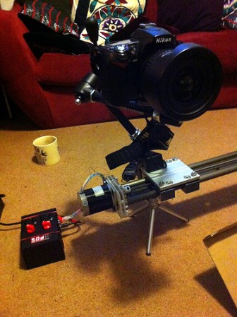
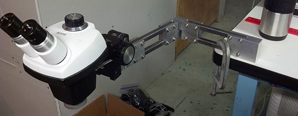
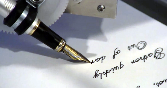
The machine uses a gantry to move the writing tip along the X and Y axes. The flexible-nib calligraphy pen is mounted on a sprocket which rotates the tip onto the writing surface, taking care of the third axis. The rig was beautifully rendered from their CAD drawings, then tweaked to ensure the smoothest motion possible before the quintet of Sophomores began the physical build.
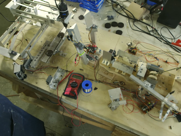
The drive hardware is very simple yet it produces great results. It uses an Arduino along with three stepper motor drivers. There are also limiting switches to protect the hardware from runaway code. The software interface designed by the team lets the user cut and paste their text, and select a font, font size, alignment, etc. It then converts the text to G-code and pushes it to the Arduino where the GRBL package takes care of business.
Don’t miss the device in action, writing out a [Langston Hughes] work in the clip after the break.
Continue reading “Handwriting Suck? Build A Machine To Do It For You”