Cyberdecks rock because their homebrewed nature lets them feature all kinds of nifty additional functionality. [Kaushlesh] has built his deck with an eye to ham radio use, and it’s a rugged and impressive thing.
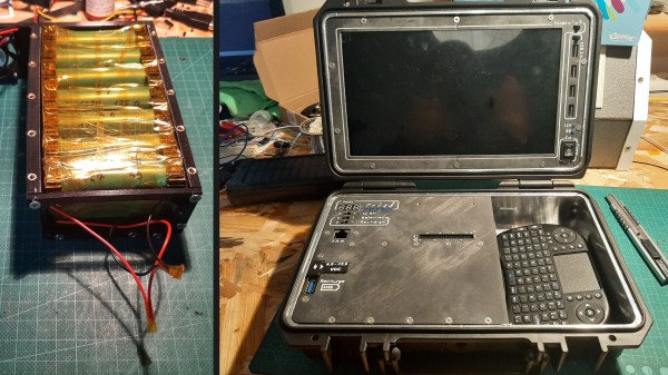
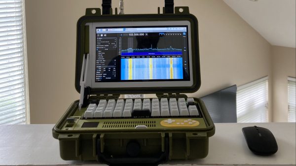
The deck is built into a weatherproof enclosure, with various 3D-printed parts helping to integrate the components into the clamshell enclosure. It runs on a Raspberry Pi 4, with [Kaushlesh] springing for the hefty model with 8GB of RAM. It has a 10-inch LCD screen and a rechargable battery pack with an impressive 20 hour battery life, and is intended for use when [Kaushlesh] is out camping or participating in ham radio field days. To that end, it’s equipped with a USB software-defined radio module and a BNC connector for hooking up an external antenna. It also has a game controller that mounts inside, just in case he desires playing a few games on Retropie while he’s out and about. It’s even got storage for a mouse and rocks a decent-sized keyboard inside.
We’d love to tote this to a hamfest for a bit of hacking on the side. It’s not the first ham-themed cyberdeck we’ve seen, either. Now we just need one built for prosciutto. Video after the break.
Continue reading “2023 Cyberdeck Challenge: A Ham Radio Cyberdeck”