This excellent content from the Hackaday writing crew highlights recurring topics and popular series like Linux-Fu, 3D-Printering, Hackaday Links, This Week in Security, Inputs of Interest, Profiles in Science, Retrotechtacular, Ask Hackaday, Teardowns, Reviews, and many more.
After two years in remote mode, we’re very excited to announce that this year’s Hackaday Supercon will be coming back, live! Join us Nov. 4th, 5th, and 6th in sunny Pasadena, CA for three days of hacks, talks, and socializing with the Hackaday community. And we’d love to see and hear in person what you’ve been up to for the last two years – so start brainstorming what you’re going to talk about now and fill out the call for proposals.
Supercon is On!
We’ll be starting off on Friday Nov. 4th with early-bird registration, a mellow afternoon of badge-hacking and workshops, and a party to kick off the con. Saturday and Sunday will be the full enchilada: two tracks of talks, hacking stations and food set up in the alley, and workshops aplenty. (Just thinking about hacking in the alley and sharing tacos afterward again brings a tear of joy to my eye.) We’ll close up Sunday night with the 2022 Hackaday Prize Awards and a chance to demo the weekend’s badge hacking on stage.
If you haven’t ever been to a Supercon before, it’s Hackaday in real life. People bring hacks to show and share, projects to work on, and their ideas that are too big to fit in the overhead compartment anyway. The crowd is awesome. There are seasoned pros, famous YouTubers, and brand-new hackers to boot. But yet it’s not overwhelming – Supercon is too big to fit in your living room, but it’s nonetheless cozy. The folks in attendance are all fantastic and you’ll stumble into the most awesome conversations.
It’s a weekend you don’t want to miss, so start figuring out how you’re going to get to Pasadena now.
The folks at NASA are taking a well-deserved victory lap this week after the splashy reveal of the first scientific images from the James Webb Space Telescope. As we expected, the first public release included a lot of comparisons to images obtained from Hubble, as the general public understandably sees Webb as the successor to the venerable space telescope, now in its third decade of service. So for a “let’s see what this baby can do” image, they turned Webb loose on a tiny patch of sky in the southern hemisphere containing galactic cluster SMACS 0723, and sent back images and spectroscopic data from galaxies up to 13 billion light years away. There are plenty of analyses of Webb’s deep field and the other images in the first release, but we particularly liked the takes by both Anton Petrov and Dr. Becky. They both talk about the cooler scientific aspects of these images, and how Webb is much more than just a $10 billion desktop image generator.
We here at Hackaday are super-duper proponents of open source. Software, hardware, or firmware, we like to be able to see it, learn from it, modify it, and make it ourselves. Some of this is self-serving because when we can’t see how it was done, we can’t show you how it’s done. But it’s also from a deeper place than that: the belief that the world is made better by sharing and open access.
One of the pieces of open-source firmware that I have running on no fewer than three devices in my house right now is grbl – it’s a super-simple, super-reliable G-code interpreter and stepper motor controller that has stood the test of time. It’s also GPL3 licensed, which means that if you want to use the code in your project, and you modify it to match your particular machine, you have to make the modified version available for those who bought the machine to modify themselves.
Good news incoming! Norbert wrote in the comments that since the post hit Hackaday, they’ve taken notice over at Ortur and have gotten back in touch with him. Assuming that they’re on their way to doing the right thing, this could be a nice win for grbl and for Ortur users alike.
Inside the free software world, we all know that “free” has many meanings, but I’d bet that you don’t have to go far outside our community to find people who don’t know that “free” software can have tight usage restrictions on it. (Or maybe not – it all depends on the license that the software’s author chose.) Reading software licenses is lousy work better left for lawyers than hackers anyway, and I can no longer count how many times I’ve clicked on a EULA without combing through it.
So what Norbert did was a good deed – educating a company that used GPL software of their obligations. My gut says that Ortur had no idea what they needed to do to comply with the license, and Norbert told them, even if it required some public arm-twisting. But now, Ortur has the opportunity to make good, and hackers everywhere can customize the firmware that drives their laser engravers. Woot!
It’s probably too early to declare victory here, but consider following Norbert’s example yourself. While you can’t bring a lawsuit if you’re not the copyright owner, you can still defend your right to free software simply by explaining it politely to companies that might not know that they’re breaking the law. And when they come around, make sure you welcome them into the global open-source hive mind, because we all win. One of us!
This article is part of the Hackaday.com newsletter, delivered every seven days for each of the last 200+ weeks. It also includes our favorite articles from the last seven days that you can see on the web version of the newsletter.
Want this type of article to hit your inbox every Friday morning? You should sign up!
The average person’s perception of a ham radio operator, assuming they even know what that means, is more than likely some graybeard huddled over the knobs of a war-surplus transmitter in the wee small hours of the morning. It’s a mental image that, admittedly, isn’t entirely off the mark in some cases. But it’s also a gross over-simplification, and a generalization that isn’t doing the hobby any favors when it comes to bringing in new blood.
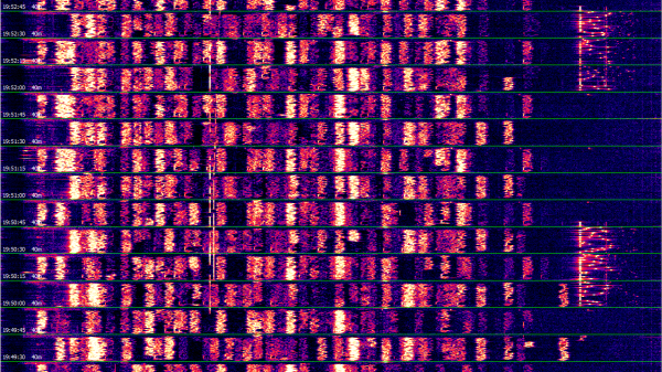
In reality, a modern ham’s toolkit includes a wide array of technologies that are about as far away from your grandfather’s kit-built rig as could be — and there’s exciting new protocols and tools on the horizon. To ensure a bright future for amateur radio, these technologies need to be nurtured the word needs to be spread about what they can do. Along the way, we’ll also need to push back against stereotypes that can hinder younger operators from signing on.
On the forefront of these efforts is Amateur Radio Digital Communications (ARDC), a private foundation dedicated to supporting amateur radio and digital communication by providing grants to scholarships, educational programs, and promising open source technical projects. For this week’s Hack Chat, ARDC Executive Director Rosy Schechter (KJ7RYV) and Staff Lead John Hays (K7VE) dropped by to talk about the future of radio and digital communications.
Rosy kicked things off with a brief overview of ARDC’s fascinating history. The story starts in 1981, when Hank Magnuski had the incredible foresight to realize that amateur radio packet networks could benefit from having a dedicated block of IP addresses. In those early days, running out of addresses was all but unimaginable, so he had no trouble securing 16.7 million IPs for use by licensed amateur radio operators. This block of addresses, known as AMPRNet and then later 44Net, was administered by volunteers until ARDC was formed in 2011 and took over ownership. In 2019, the decision was made to sell off about four million of the remaining IP addresses — the proceeds of which went into an endowment that now funds the foundation’s grant programs.
Of all the recipients of ARDC grants, the M17 project garnered the most interest during the Chat. This community of open source developers and radio enthusiasts is developing a next-generation digital radio protocol for data and voice that’s unencumbered by patents and royalties. In their own words, M17 is focused on “radio hardware designs that can be copied and built by anyone, software that anyone has the freedom to modify and share to suit their own needs, and other open systems that respect your freedom to tinker.” They’re definitely our kind of folks — we first covered the project in 2020, and are keen to see it develop further.
John says the foundation has approximately $6 million each year they can dole out, and that while there’s certainly no shortage of worthwhile projects to support as it is, they’re always looking for new applicants. The instructions and guides for grant applications are still being refined, but there’s at least one hard requirement for any project that wants to be funded by the ARDC: it must be open source and available to the general amateur population.
Of course, all this new technology is moot if there’s nobody to use it. It’s no secret that getting young people interested in amateur radio has been a challenge, and frankly, it’s little surprise. When a teenager can already contact anyone on the planet using the smartphone in their pocket, getting a ham license doesn’t hold quite the same allure as it did to earlier generations.
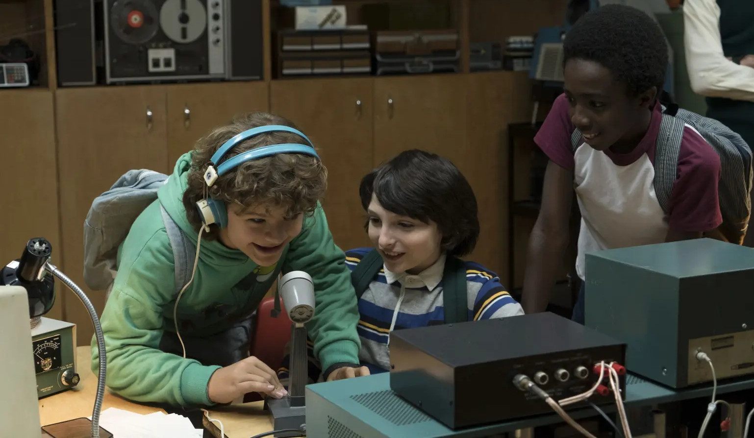
Depending on how old you are, this might have been one of the most shocking moments in Stranger Things.
The end result is that awareness among youth is low. During the Chat, one participant recounted how he had to put Netflix’s Stranger Things on pause so he could explain to his teenage son how the characters in the 1980s set show were able to communicate across long distances using a homemade radio. Think about that for a minute — in a show about nightmarish creatures invading our world from an alternate dimension, the hardest thing for this young man to wrap his head around was the fact a group of teenagers would be able to keep in touch with each other without the Internet or phone lines to connect them.
So its no surprise that John says the ARDC is actively looking for programs which can help improve the demographics of amateur radio. The foundation is looking to not only bring younger people onboard, but also reach out to groups that have been traditionally underrepresented in the hobby. As an example, he points to a grant awarded to the Bridgerland Amateur Radio Club (BARC) last year to bolster their youth engagement program. Funds went towards putting together a portable rig that would allow students to communicate with the International Space Station, and the development of hands-on workshops where teens will be able to launch, track, and recover payloads on a high altitude balloon. Let’s see them do that on their fancy new smartphone.
We want to not only thank Rosy Schechter and John Hays for taking part in this week’s Hack Chat, but everyone else at Amateur Radio Digital Communications for their efforts to support the present and future of amateur radio and digital communication.
The Hack Chat is a weekly online chat session hosted by leading experts from all corners of the hardware hacking universe. It’s a great way for hackers connect in a fun and informal way, but if you can’t make it live, these overview posts as well as the transcripts posted to Hackaday.io make sure you don’t miss out.
This week, Editor-in-Chief Elliot Williams and Assignments Editor Kristina Panos stood around talking like they weren’t thousands of miles apart. And we mean that literally: Kristina just got an up/down desk, and it turns out that Elliot’s had the exact same one for years.
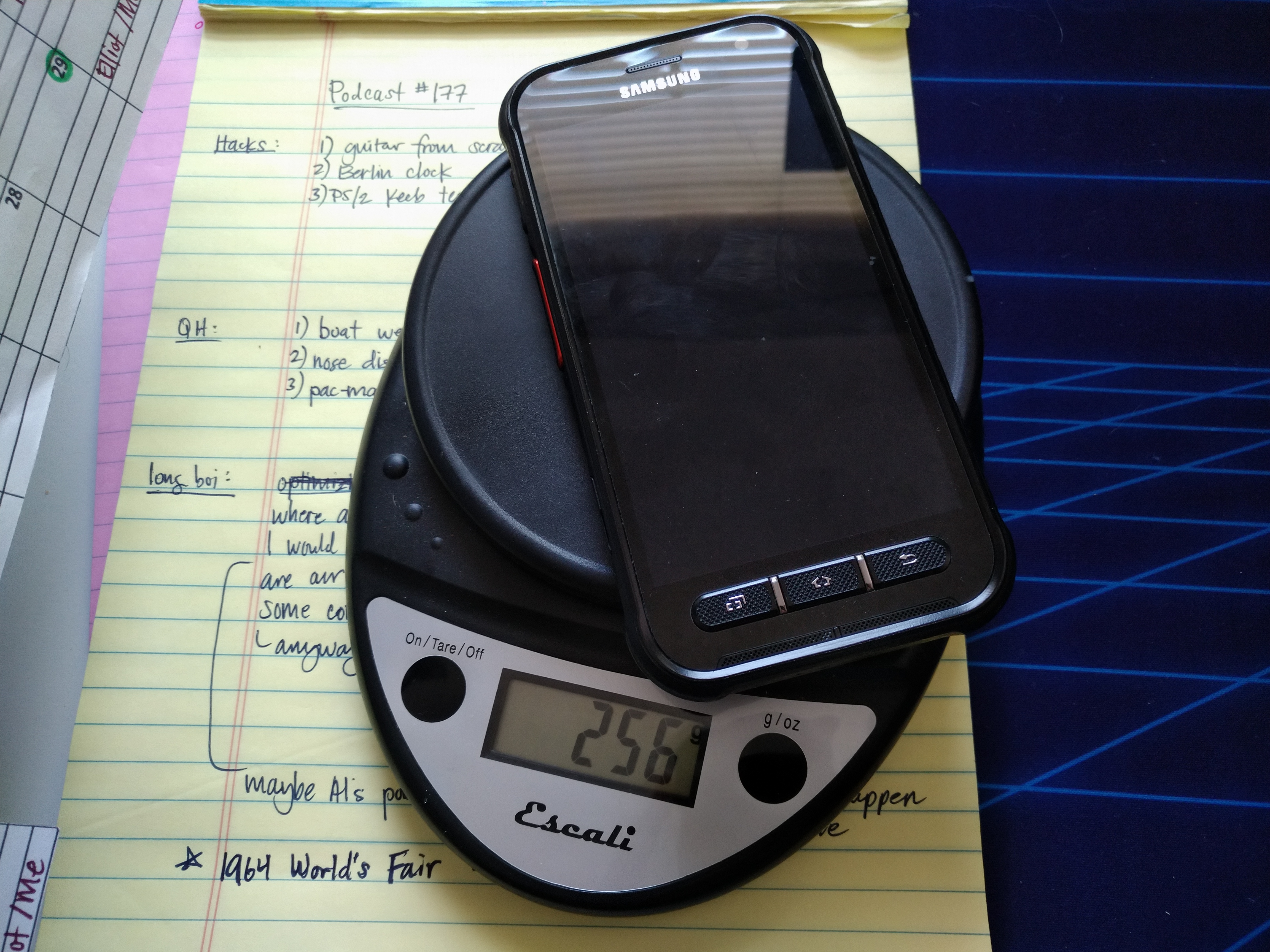
Kristina’s phone is heavier than yours.
In between the hammerings on Kristina’s house (she’s getting new siding), we kick things off by drooling over the first images from the James Webb Space Telescope, and compare a few of them to the same shots from Hubble.
We managed to save a bit of saliva for all the seriously swell keyboards and not-keyboards we saw throughout the Odd Inputs and Peculiar Peripherals contest, all of which are winners in our book.
This week, we ask the tough questions, like why would someone who has never played guitar want to build one from scratch? We can only guess that the answer is simply, ‘because l can’. As lazy as that reasoning may sound, this build is anything but.
Later on, we’ll ogle an ocean of PS/2 keyboards and their new owner’s portable testing rig, complain about ASMR, and laugh about a giant nose that sneezes out sanitizer.
The Odd Inputs and Peculiar Peripherals Contest wrapped up last week, and our judges have been hard at work sifting through their favorite projects. And this was no easy task – we had 75 entries and so many of them were cool in their own right that all we can say is go check them all out. Really.
But we had to pick winners, not the least because Digi-Key put up three $150 gift certificates. So without further ado, here are the top three projects and as many honorable mentions as you have fingers and toes – if you don’t count your thumbs.
The Prize Winners
Keybon should be a mainstream commercial product. It’s a macro keypad with an OLED screen per key. It talks to an application on your desktop that detects the program that you currently have focused, and adapts the keypress action and the OLED labels to match. It’s a super-slick 3D-printed design to boot. It’s the dream of the Optimus Maximus, but made both DIY and significantly more reasonable as a macro pad. It’s the coolest thing to have on your desk, and it’s a big winner!
On the ridiculous side of keyboards, meet the Cree-board. [Matt] says he got the idea of using beefy COB LEDs as keycaps from the bad pun in the name, but we love the effect when you press down on the otherwise blinding light – they’re so bright that they use your entire meaty finger as a diffuser. Plus, it really does look like a keypad of sunny-side up eggs. It’s wacky, unique, and what’s not to love about that in a macropad?
Finally, [Josh EJ] turned an exercise bike into a wireless gamepad, obliterating the choice between getting fit and getting high scores by enabling both at the same time. An ESP32-turned-Bluetooth-gamepad is the brains, and he documents in detail how he hooked up a homebrew cadence sensor, used the heart-rate pads as buttons, and even added some extra controls on top. Watching clips of him pedaling his heart out in order to push the virtual pedal to the metal in GRID Autosport, we only wish he were screaming “vroooom”. Continue reading “Overwhelmed By Odd Inputs: The Contest Winners And More”→

 If you haven’t ever been to a Supercon before, it’s Hackaday in real life. People bring hacks to show and share, projects to work on, and their ideas that are too big to fit in the overhead compartment anyway. The crowd is awesome. There are seasoned pros, famous YouTubers, and brand-new hackers to boot. But yet it’s not overwhelming – Supercon is too big to fit in your living room, but it’s nonetheless cozy. The folks in attendance are all fantastic and you’ll stumble into the most awesome conversations.