This excellent content from the Hackaday writing crew highlights recurring topics and popular series like Linux-Fu, 3D-Printering, Hackaday Links, This Week in Security, Inputs of Interest, Profiles in Science, Retrotechtacular, Ask Hackaday, Teardowns, Reviews, and many more.
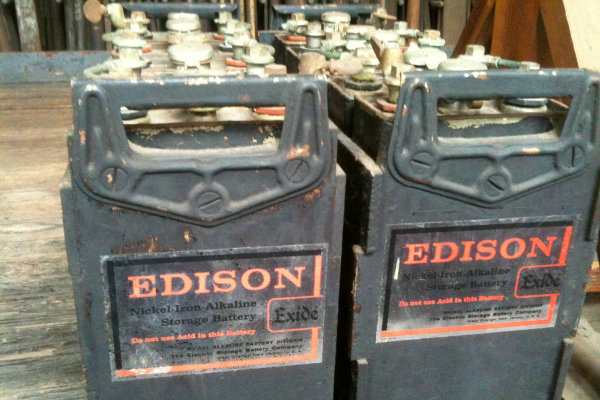
Excited about your new electric vehicle? Thomas Edison would be, too. He tried to produce electric vehicles for Ford around 1900. Petroleum-based vehicles dashed his dreams of the electric car, and the battery he wanted to use languished as a technological dead end. The batteries were long-lasting, sure, but they were expensive and had other problems, not the least of which was producing hydrogen gas. But that battery technology is receiving renewed interest today, because some of the things that made it a bad car battery make it good for alternate energy projects.
One of the joys of an itinerant existence comes in periodically being reunited with the fruits of various orders that were sent to hackerspaces or friends somewhere along the way. These anonymous parcels from afar hold an assortment of wonders, with the added element of anticipation that comes from forgetting exactly what had been ordered.
So it is with today’s subject, a Mustool MT525 electromagnetic radiation tester. At a cost not far above £10 ($13.70), this was an impulse purchase driven by curiosity; these devices claim to measure both magnetic and electric fields, but what do they really measure? My interest in these matters lies in the direction of radio, but I have never examined such an instrument. Time to subject it to the Hackaday treatment.
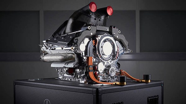
In 2014, Formula 1 switched away from V8 engines, electing instead to mandate all teams race with turbocharged V6 engines of 1.6 litres displacement, fitted with advanced energy recovery systems. The aim was to return Formula 1 to having some vague notion of relevance to modern road car technologies, with a strong focus on efficiency. This was achieved by mandating maximum fuel consumption for races, as well as placing a heavy emphasis on hybrid technology.
The Mercedes W05 Hybrid was the first of 7 championship-winning F1 cars from the British-based, German-funded team. It quickly showed the value of the team’s split-turbo technology.
Since then, Mercedes have dominated the field in what is now known as the turbo-hybrid era. The German team has taken home every drivers and constructors championship since, often taking home the crown well before the season is over. Much has been made of the team’s engine as a key part of this dominance, widely considered to be more powerful and efficient than the competition at all but a few select races in the last seven years, and much of the credit goes to the company’s innovative split-turbo system. Today, we’ll explore why the innovation was such a game changer in Formula 1.
This time I promise I only have a couple of stories from Elon Musk’s company. SpaceX’s latest Starship test launch ended in another explosion, proving that space hardware remains hard to get right. We’ll keep watching as they keep launching, and it can’t be long until they’ve ironed out all the problems. Meanwhile there’s brighter news from the company’s Crew Dragon, a modified version of the capsule with the forward docking ring replaced by a transparent dome is planned for launch in September with the company’s first flight carrying civilian passengers. It’s doubtless unwelcome news for Virgin Galactic, whose suborbital passenger flights are edging closer to reality with the unveiling of their first SpaceShip III craft. Finally, a Falcon 9 upper stage broke up on re-entry over the northwestern USA, giving observers on the ground a spactacular show.
Spectacular view of the Falcon 9 debris. Via Lu Jerz
Meanwhile up there in orbit there have been found on the ISS some strains of bacteria previously unknown to scientists on Earth, but it’s not yet time to panic about Mutant Bugs From Space. It seems these bacteria are of a type that is essential in the growing of plants, so it’s likely they originally hitched a ride up with one of the several plant-growing experiments that have taken place over the station’s lifetime. Staying on the ISS, astronauts visiting the station have been at the centre of a recently published study looking at loss of bone density over long periods in space. The bone experts found that bone density could still be lost despite the astronauts’ in-flight exercise programs, and concluded that exercise regimes pre-flight should be taken into account for future in-orbit exercise planning.
Further away from Earth, the ESA Mars Express satellite has been used for a multi-year study of water loss to space from the Martian atmosphere. The ESA scientists identified the seasonal mechanism that leads to the planet’s upper atmosphere having an excess of water and in particular the effect of the periodic planet-wide dust storms on accelerating water loss, but failed to account for the water that they estimate Mars must have lost over its history. From a study of water-created surface features they can estimate how much liquid the planet once had, yet the atmospheric losses fail to account for it all. Has it disappeared underground? More studies are required before we’ll have an answer.
The exciting news over the coming days will no doubt be the Ingenuity Martian helicopter, which we have seen slowly unfolding itself prior to unloading from the belly of the Perseverence rover. If all goes according to plan the little craft will be set down before the rover trundles off to a safe distance, and the historic flight will take place on April 8th. We’ll be on the edges of our seats, and no doubt you will be, too.
Of all our senses, the sense of touch is perhaps the most underappreciated. We understand and accept the tragedy that attends loss of vision or hearing, and the impact on the quality of life resulting from olfactory and gustatory sensations can be severe. But for some reason, we don’t give a second thought to our sense of touch, which is indeed strange given that we are literally covered with touch sensors. That’s a bit of a shame, since touch can reveal so much about the world around us, and our emotional well-being is so tightly tied to the tactile senses that those deprived of it in infancy can be scarred for life.
Haptics is the technology of tactile feedback, which seeks to leverage the human need for tactile experiences to enrich the experience of dealing with the technological world. Haptic feedback devices are everywhere now, and have gone far beyond the simple off-balance motor used since the days when a pager was a status symbol. To help us sort out what’s new in the haptics world, Tim and Kyle from Nanoport Technology will stop by the Hack Chat. Nanoport is a company on the cutting edge of haptics, so they’ll have a wealth of details about what haptics are, where the field is going, and how you can start thinking about making touch a part of your projects.
Click that speech bubble to the right, and you’ll be taken directly to the Hack Chat group on Hackaday.io. You don’t have to wait until Wednesday; join whenever you want and you can see what the community is talking about. Continue reading “Haptics Hack Chat With Nanoport Technology”→
Can I just say that doing a links roundup article in a week that includes April Fool’s Day isn’t a fun job? Because it’s not. I mean, how can you take something like reports of X-rays flowing from Uranus seriously when they release the report on such a day? It sure looks like a legitimate story, though, and a pretty interesting one. Planets emitting X-rays isn’t really a new thing; we’ve known that Jupiter and Saturn are both powerful X-ray sources for decades. Even though Uranus is the odd child of our solar system, finding evidence for X-ray emissions buried in data captured by the Chandra observatory in 2007 was unexpected. Astronomers think the X-rays might be coming from Uranus’ rings, or they might be reflections of X-rays streaming out from the sun. Or, it might be the weird alignment of the gas giant’s magnetic field causing powerful aurorae that glow in the X-ray part of the spectrum. Whatever it is, it’s weird and beautiful, which all things considered isn’t a bad way for things to be.
Another potential jest-based story popped up this week about the seemingly impossible “EmDrive”. It seems that when you appear to be breaking the laws of physics, you’re probably doing it wrong, and careful lab tests showed that fuel-free propulsion isn’t here yet. One would think it was self-obvious that filling a closed asymmetrical chamber with microwaves would produce absolutely no thrust, but EmDrive proponents have reported small but measurable amounts of thrust from the improbable engine for years. A team at TU Dresden found otherwise, though. Even though they were able to measure a displacement of the engine, it appears to be from the test stand heating up and warping as the RF energy flowed into the drive chamber. By changing the way the engine was supported, they were able to cancel out the dimensional changes that were making it look like the EmDrive was actually working.
Want to use surface-mount parts, but don’t want to bother spinning up an SMD board? Not a problem, at least if you follow the lead of David Buchanan and perform no-surface surface-mount prototyping. We stumbled upon this on Twitter and thought it looked cool — it’s got a little bit of a circuit sculpture feeling, and we like the old-school look of plain 0.1″ perfboard. David reports that the flying leads are just enameled magnet wire; having done our share of scraping and cleaning magnet wire prior to soldering, we figured that part of the build must have been painful. We pinged David and asked if he had any shortcuts for prepping magnet wire, but alas, he says he just used a hot blob of solder and a little patience while the enamel cooked off. We still really like the style of this build, and we applaud the effort.
Speaking of stumbling across things, that’s one of the great joys of this job — falling down algorithmically generated rabbit holes as we troll about for the freshest hacks. One such serendipitous was this YouTube channel documenting a really nice jet engine build. We’ve seen plenty of jet engines before, but very few with afterburners like this one has. There’s also something deeply satisfying about the variable-throat nozzle that Praendy built for the engine — it’s a level of complexity that you don’t often see in hobbyist jet engines, and yet the mechanism is very simple and understandable.
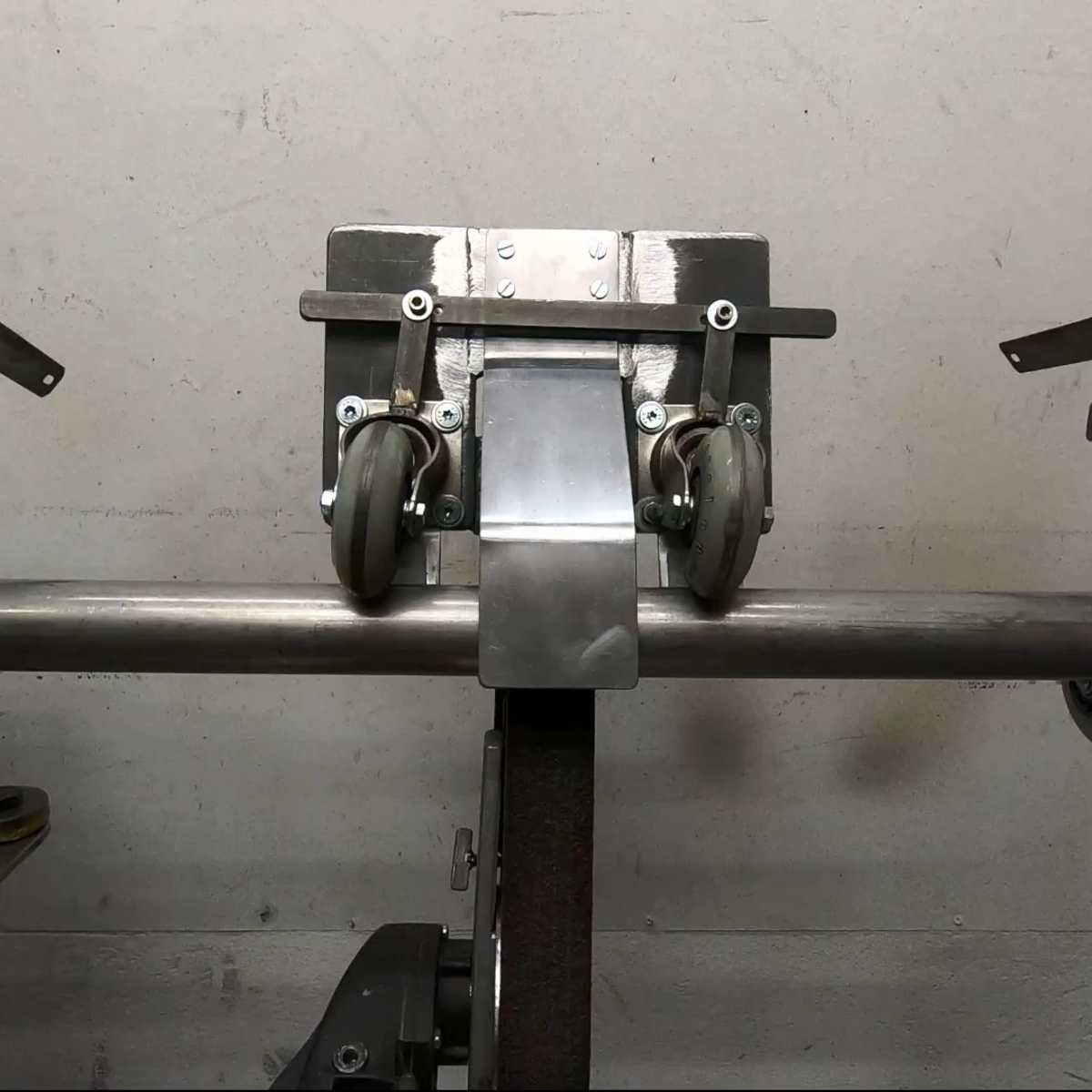
The other rabbit hole we discovered was after reporting on this cool TIG tungsten grinding tool. That took us into The Metalist’s back catalog, where we found a lot of interesting stuff. But the real treat was this automatic tube polisher (video), which we have to say kept us guessing up to the very end. If you’ve got 12 minutes and you enjoy metalworking builds at all, watch it and see if you’re not surprised by the cleverness of this tool.
And finally, we had heard of the travails of Anatoli Bugorski before, but never in the detail presented in this disturbing video. (Embedded below.)
Who is Anatoli Bugorski, you ask? He is a Russian particle physicist who, while working in an accelerator lab in 1978, managed to get his head directly in the path of a 76 GeV proton beam. Despite getting a huge dose of radiation, Bugorski not only survived the accident but managed to finish his Ph.D. and went on to a long career in nuclear physics. He also got married and had a son. He was certainly injured — facial paralysis and partial deafness, mainly — but did not suffer anything like the gruesome fates of the Chernobyl firefighters or others receiving massive radiation doses. The video goes into some detail about how the accident happened — two light bulbs are better than one, it turns out. We enjoyed the video, but couldn’t stop thinking that Bugorski was the Russian atomic-age equivalent of Phineas Gage.
I’m a firm believer in using the right tool for the job. And one of the most fantastic things about open-source software tools is that nothing stops you from trying them all. For instance, I’ve been going back and forth between a couple, maybe three, CAD/CAM tools over the past few weeks. They each have their strengths and weaknesses, and so if I’m doing a simpler job, I use the simpler software, because it’s quicker and, well, simpler. But I’ve got to cut it out, at least for a while, and I’ll tell you why.
The first of the packages is FreeCAD, and it’s an extremely capable piece of CAD/CAM software. It can do everything, or so it seems. But it’s got a long shallow learning curve, and I’m only about halfway up. I’m at the stage where I should be hammering out simple “hello world” parts for practice. I say, I should be.
Fortunately/unfortunately, some Hackaday readers introduced me to KrabzCAM through the comments. It’s significantly less feature-full than FreeCAD, but it gets the job of turning your wife’s sketches of bunnies into Easter decorations done in a jiffy. For simple stuff like that, it’s a nice simple tool, and is the perfect fit for 2D CAM jobs. It’s got some other nice features, and it handles laser engraving nicely as well. And that’s the problem.
Doing the simple stuff with KrabzCAM means that when I do finally turn back to FreeCAD, I’m working on a more challenging project — using techniques that I’m not necessarily up to speed on. So I’ll put the time in, but find myself still stumbling over the introductory “hello world” stuff like navigation and project setup.
I know — #first-world-hacker-problems. “Poor Elliot has access to too many useful tools, with strengths that make them fit different jobs!” And honestly, I’m stoked to have so many good options — that wasn’t the case five years ago. But in this case, using the right tool for the job is wrong for me learning the other tool.
On reflection, this is related to the never-try-anything-new-because-your-current-tools-work-just-fine problem. And the solution to that one is to simply bite the bullet and stick it out with FreeCAD until I get proficient. But KrabzCAM works so well for those small 2D jobs…
A hacker’s life is hard.
This article is part of the Hackaday.com newsletter, delivered every seven days for each of the last 200+ weeks. It also includes our favorite articles from the last seven days that you can see on the web version of the newsletter.
Want this type of article to hit your inbox every Friday morning? You should sign up!