This excellent content from the Hackaday writing crew highlights recurring topics and popular series like Linux-Fu, 3D-Printering, Hackaday Links, This Week in Security, Inputs of Interest, Profiles in Science, Retrotechtacular, Ask Hackaday, Teardowns, Reviews, and many more.
A few weeks ago, we took a look at the best badge hacks at the Hackaday Supercon. These were the best badge hacks anyone has ever seen – including what comes out of DEF CON and the SDR badge from the latest CCC. I’m ascribing this entirely to the free-form nature of the badge; give people a blank canvas and you’re sure to get a diverse field of builds. Now it’s time to take a look at the cream of the crop, hear what the jolly wrencher sounds like, and how to put 1000 Volts in a badge.
There were three categories for the badge hacking competition at the SuperCon – best deadbug, best blinky, and most over the top. A surprising number of people managed to solder, glue, and tape some components to a the piece of FR4 we used as a conference badge, but in the end, only three would win.
About eight years before the Xerox built the Alto at PARC and over a decade before the Apple ][ premiered, Italian business equipment manufacturer Olivetti produced a bona fide desktop personal computer. When Olivetti debuted this typewriter-sized marvel in 1965 at a business convention in New York City, people were in absolute awe that this tiny, self-contained unit could perform the same types of functions as the hulking room-sized mainframes of the time. Some were sure that it was simply a small input device for a much bigger machine hiding behind the curtain.
But the revolutionary Olivetti Programma 101 was no joke. It performed standard four-banger operations and could handle square root and absolute value calculations. The Olivetti had 16 jump instructions as well as 16 conditional jump instructions, which put it firmly in state machine territory. Programs could be printed on a roll of paper or stored long-term on long magnetic cards.
A recent post by [Christian Heilmann] is one of several I’ve read lately talking about how Web sites–Stack Overflow, in particular–are breeding a new kind of developer. The kind of developer that simply copies and pastes example code or schematics with no real understanding of what’s going on. His conclusion is that developers who don’t fully understand what they are doing will become disinterested and burn out. He’s talking about software developers, but I think you could extend the argument to developers of all kinds, including hardware hackers. He concluded that–at least while learning–you stick to the old ways of doing things.
I have trouble disagreeing with [Christian] on the details, but I do disagree with the conclusion. People have copied work from other sources for a very long time. We’ve all seen circuits that were clearly either torn from a datasheet or even glued together from multiple datasheet examples way before there was an Internet.
There’s two things that are slightly different today: First, everyone has easy access to lots of examples. You don’t have to go find a book (possibly at a library), search through it, and find one or two examples. A quick Google will find dozens or hundreds of examples.
The second thing that is different is that there are places exist like Stack Overflow where you don’t even have to go looking. You can simply ask, “How do I do X?” and you will get answers from someone. It might be wrong. You might not understand it. But you’ll probably get some kind of answer.
Software hackathons are an old hat these days. They’re a great scouting opportunity for talented candidates looking for a job, and they provide the battleground for coding enthusiasts to prove themselves by developing a project from start to finish overnight, albeit, with a few kinks. Hardware hackathons are an entirely different beast. By trading APIs for components and Python libraries for soldering irons, they pull the excitement out of the text editor and onto the workbench for everyone to see.
This article was written for the Omnibus vol #02 Order yours now
While hardware hackathons might be “the next big thing” with you and your four best DIY-pals, the broad range of physical components, from Arduinos to CNC milling time, makes rule-establishment, safety enforcement, and winning criteria far more difficult to constrain within a single night. Enter Muddhacks. This past October, three students from Harvey Mudd College set out to deliver a hardware hackathon that would open their student community’s mind to the thought of tinkering-for-fun in their spare time outside the lab and beyond their homework.
Students [Benjamin Chasnov], [Apoorva Sharma], and [Akhil Bagaria] had just finished their experimental engineering class: E80. Along the way, they designed a custom sensor payload into a meter-long rocket and launched both rocket and payload to measure the rocket’s fundamental frequencies in flight. With a victory behind them, they were ready for their next big project.
(Left to right) [Ben], [Apoorva], and [Akhil] stare skyward as their rocket launch sets them hungry for future projects.As the next semester waned onwards, however, they realized that any big project–no matter how modular–would be a serious time commitment. After some thought, they refactored their idea entirely. Tinkering was a passion shared by each of them; why not spread the love school-wide and bring together a community of engineers-by-night? To resolve their craving for after-hours engineering and to inspire a culture of collaborative tinkering, they set out to bootstrap a hardware hackathon; an event where many projects could be realized by many students in a single night.
Everyone Says Hardware is Hard
For the unitiated, hardware looks hard. Breadboards, LEDs, r`esistors? To those who have never put together a simple circuit before, taking that first leap is a challenge set by a box of components that almost seems to glare back menacingly. The three teammates took this first-timer roadblock as a challenge unto themselves to break down that barrier. Thus, HackWeek was born.
HackWeek was the MuddHacks teams’ answer to get students comfortable gluing modules together to produce a functional project in a short time. How do I make things move? How do I connect things to the internet? What parts do I choose? All of these questions-worth-answering became topics of the three-day event before the hackathon. The idea behind HackWeek was simple: give eager students enough theory and a functional demo that they could probe, tweak, and recompile so that they could feel more comfortable developing their own ideas into projects. On day one, the MuddHacks team brought functional demos of various motors into the hands of eager students. By day two, the three teammates actually assembled a functional hack of their own before the eyes of their listeners: an internet-enabled microwave that could remotely start warming up that cup of ramen on your way back from class.
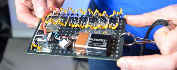
[Akhil], [Ben], and [Apoorva] bring the Phone-Microwave to life at HackWeek while users try to fire it up remotely.Unlike software hackathons, a successful hardware hackathon involves parts, and the MuddHacks team was well-prepared to bring the participants the parts that they wanted. With ten days to go before the event, [Ben] took orders from each team’s desired list of parts. With a day to go, all parts arrived before the event and made it to their respective user’s hands in “goodie bags” on the last day of HackWeek. On this last day, teams opened their bags and explored the parts given to them and to other teams while taking advice from the mentors present to offer tips for using various components. This time for “open-exploration” ensured that the following night spent hacking would be more fruitful, now that teams had cleared the starting questions for various parts on the previous day.
On the night of MuddHacks, [Ben], [Apoorva], and [Akhil] had completely turned their original aim to build their own project into a night spent mentoring the projects of others. Throughout the night, they became the “ground crew,” bringing advice to debugging teams and keeping the night culture alive with two waves of snacks. “We felt that if students were going to come to our event, it was our responsibility to keep them both awake and happy,” Apoorva mentioned. Classrooms refilled for the night with students eager to bring their robots, LEDs, and gantries to life, but other parts of the school came to life as well. The machine shops reopened, and old oscilloscopes and test equipment emerged from the engineering stock room for loan to any teams that needed them. Even a few professors happened to wander into classrooms and offer advice.
For [Ben], [Apoorva], and [Akhil], fostering a sense of community in tinkering became their top priority. As they wandered between teams, they encouraged stellar performers to take a brief break and help out another team through a bug. At the night’s end, a number of early-rising professors joined the crowd of students to judge the winners. Oddly enough, the MuddHacks team didn’t spend any money on the prizes–but no one seemed to notice or care. For the eighth of the entire undergraduate student body that attended, these students weren’t coming for the prizes. They came to join that culture of tinkerers–to be a fellow hardware-hacker-by-night–eager to do their part to make the world blink.
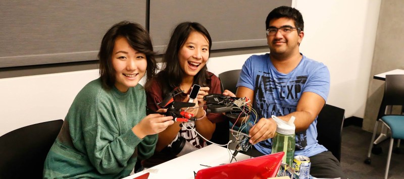
(Left to right) Erin Paeng, Cherie Ho, and Shaan Gareeb take first place by rewiring an rc helicopter for hand-control with a Leap Motion
How to Deliver a Hardware Hackathon
When was the last time you burned yourself downloading someone else’s API? Probably never. With a hardware hackathon, comes a new wave of challenges not seen before in the software variant. With one successful hackathon under their belt, we asked the MuddHacks Team to share some insights for other teams looking to assemble their own hardware hackathon. Here’s what they came up with.
Getting Funding
Charging participants an entrance fee may solve the problem of funding, but for the thrifty, starving student, entrance fees may also weed out people who had a slight curiosity but weren’t eager to throw a few bucks down to support it. The solution? Bring participants in for free and support the hackathon with external funding. The MuddHacks team reached out to a number of companies and encouraged them to take a sincere look at their website and cause.
Administrivia
The Muddhacks team handled most of their administrative work online. Among the tools they chose were
Google Forms for parts orders and feedback
Slack and email lists for real-time updates during the event
Google Spreadsheets for keeping track of order requests
Bootstrap for deploying a website
Assembling Teams
The Muddhacks team mandated that students form teams to enter the hackathon, mostly to foster community and collaboration. They reasoned: “If you already build things for fun on your own, you don’t need a hackathon to get you excited about hardware for the first time.” Most teams self-assembled, but the Muddhacks team also suggests a submission form for stragglers to pair up.
Getting Parts
Ten days before the hackathon, [Ben] put out a call to order parts in a $100 budget range. Each team made part requests, and [Ben] then ordered each of these parts in time for the hackathon. In addition, the Muddhacks team also ordered a collection of additional stock hardware (think: Arduinos and shields).
Setting the Stage
The Muddhacks team received permission to host the night event on the third floor of one of their buildings filled with classrooms. Among points to consider for the setting are:
reliable Wi-Fi connectivity
power outlet access
Safety
Soldering irons and sleep-deprivation don’t mix well. Among the points to consider for safety are tools that will keep users safe (safetly glasses and ventilation in this case). The MuddHacks team also recommends a safety waiver.
Advertising and Swag
Getting people excited is key. Logos, T-shirts, and Mugs all add to the authenticity of the one-night event. The Muddhacks Team brought in each of these to its participants. In addition, they printed posters, deployed a website and facebook page, and pitched to students directly in their computer science and engineering classes.
Keeping the Night Moving
Feed the masses. The MuddHacks team reminds us that, as the hosts and organizers of the event, it’s your responsibility to make sure that attendees are both awake and enjoying their time. Not only did the team provide two rounds of food, they also walked around and engaged participants that needed some help debugging, effectively becoming an extra set of eyes to track down bugs as mentors throughout the night.
Judging
The MuddHacks team brought in their favorite professors to judge teams’ projects. At this event, the MuddHacks team stresses that all participants deserve to see all projects. Not only can they witness something awesome, they can also engage their peers with questions, effectively learning a few extra tricks that they didn’t discover while working on their own project.
Priming for Next Year
From the MuddHacks Team: “Take pictures!” While the first website and facebook page were filled with images of the tools and the setting, next years website and advertisements could be filled with pictorial proof of the promise to participants of a genuine experience. As the first hackathon closes, they also stress that you, the organizers and founders, learn too; and the best way to do so is to collect feedback with some manner of online form. At the same time, this form could also recruit additional hands for assembling next year’s hackathon.
We hope these tips from a stellar hackathon serve as a starting point for developing one of your own. To learn more about MuddHacks, take a quick visit to their website: MuddHacks.com, or follow them on their Facebook page.
This article was specifically written for the Hackaday Omnibus vol #02. Order your copy of this limited edition print version of Hackaday.
[Camus] had it all wrong. After a few hundred years of rolling a stone up a mountain, Sisyphus would do what all humans would do: become engrossed in novelty. The stone would never reach the summit, but it could roll off some pretty sweet ramps. That mountain goat that ticked him off a few decades ago? If Sisyphus let go right now, the stone would probably take that goat out. Sisyphus, like all of us, would be consumed in meaningless novelty. One must imagine Sisyphus happy.
The pumpkin spice must flow. It’s the holidays and for a lot of us that means copious amounts of baked goods. How about an edible sandworm? It looks like something close to a cinnamon roll.
This December’s Marie Claire – whatever that is, I have no idea – features haute circuits. These circuit boards are the work of [Saar Drimer] and Boldport, makers of fine circuit board art. We’ve seen his work a number of times featuring squiggly traces and backlit panels. This seems to be the first time Boldport and the entire idea of PCB art has infiltrated the design world. He also does puzzles.
Raspberry Pi cases simply do not look cool. There’s ports coming out everywhere, and plastic really doesn’t look that great. You know what does look great? Walnut. [Karl] made a few of these out of walnut, MDF and solid aluminum. He’s thinking he might bring this to market, you can check out his webzone here.
Self-driving cars being sold right now! That’s an eBay link for a DARPA Grand Challenge vehicle, a heavily modified Isuzu VehiCross loaded up with computers, a laser scanner, camera, and connected to actuators for steering, brake, pedals, and shifter.
A few years ago, a snowboarding company realized they could use YouTube as a marketing device. They made some really cool projects, like a snowboard with battery-powered heaters embedded in the core of the board (yes, it works). There’s only so many different snowboards you can build, so they turned to surfboards. In fact, they turned to cardboard surfboards, and last week they made a cardboard electric guitar in the Fender custom shop. It’s a completely understandable linear progression from A to B to I don’t know what kind of glue they’re using.
First introduced in 2002, The iRobot Roomba was conceived as a robotic vacuum cleaner. Just about every hacker, maker, and engineer out there immediately wanted one. The Roomba proved to be more than just a vacuum though; it was the perfect base for any household robotics project. Before long Roombas were being hacked to do way more than sweep your floor. iRobot recognized this, and added a hacker friendly serial port to later model Roombas. They even released a vacuumless version called the iRobot Create. Thousands of projects have literally ridden on the wheels of the Roomba. This week’s Hacklet is all about Roomba projects.
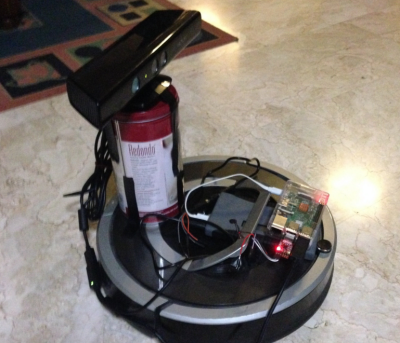
We start with [fuzzie360] and Poor Man’s Raspberry Pi Turtlebot. [Fuzzie360] has their Roomba running Robot Operating System (ROS). ROS actually is running on an on-board Raspberry Pi. While Willow Garage may be out of business, ROS lives on as an open source project run by Unbounded Robotics. Installing it can be a chore though. While [Fuzzie360] hasn’t given a full tutorial, they have offered to give advice if and when you get stuck.
A Raspberry Pi would be overkill for the simple suite of sensors built into the Roomba, but it’s perfect for [fuzzie3680’s] modified setup with a Microsoft Kinect. [Fuzzie360’s] goal is to have a robot that can vacuum the hostile territory of a university apartment.
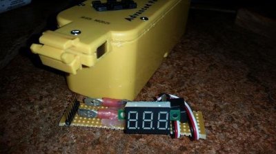
Next up is [Sircut] who upgraded his Roomba’s power cell. Early Roombas were designed to use Nickle Metal Hydride (NiMH) batteries. The individual cells are built into a proprietary iRobot battery pack. NiMH can’t hold a candle to Lithium Ion batteries though. Lithium Ion cells are very common these days in devices like cell phones and laptops. In fact, [Sircut] used 18650 sized laptop cells for this upgrade. [Sircut] also added the essential LiIon battery protection circuit to make sure those cells stay happy. A voltmeter provides a visual reference that the batteries aren’t becoming overcharged. An upgrade like this will likely double the Roomba’s runtime, but it does come at a cost. Roomba’s original charge dock can no longer be used as the on-board charge circuitry isn’t designed for LiIon battery charge algorithms.
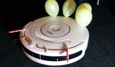
Next is [Marcel Varallo] with Robot Wars for the Commuter. How does the IT department blow off steam? Fighting robots of course! Unfortunately, [Marcel’s] coworkers aren’t all programming mavens. Hopefully some programming is in the cards for them down the road. For now though, [Marcel] has created a robot fighting league using nearly stock Roomba robots. Each bot gets a set of 3 balloons and 3 pins. A balloon represents a life. Once your lives are all popped, you’re dead! [Marcel] also created an upgrade system where winning ‘bots can move on to stronger weapons like flamethrowers. During his research, [Marcel] found out that the brushes in his Roomba are powerful enough to sweep dust and debris up without the vacuum enabled. So he’s disabled the vacuums for longer cleaning battle times.
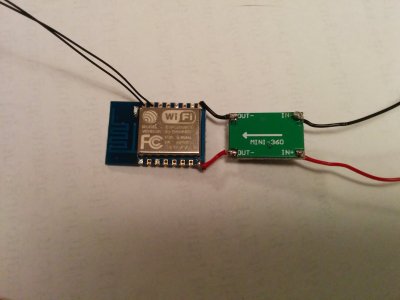
Finally we have [Fredrik Markström] and ESP8266 controlled Roomba. [Fredrick] is hacking an ESP8266 module to be the main computer of this little Robot. Of course, a ‘8266 means it will be carrying WiFi, so this robot needs to have a web interface. [Fredrik’s] first problem was powering the ESP8266. The Roomba’s battery runs around 15 volts, which is definitely not friendly to the 3.3 volt ESP8266. A switching DC to DC converter was in order, and [Fredrik] found the perfect candidate on eBay. The ‘8266 will control the Roomba through the serial interface included on all the current models. [Fredrik] has big plans for this ‘bot, including navigation and advanced vacuuming algorithms.
If you want to see more Roomba projects, check out our new Roomba project list! If I missed your project, don’t be shy, just drop me a message on Hackaday.io. That’s it for this week’s Hacklet. As always, see you next week. Same hack time, same hack channel, bringing you the best of Hackaday.io!
Just a few days after Christmas last year AirAsia Flight 8051 traveling to Singapore tragically plummeted into the sea. Indonesia completed its investigation of the crash and just released the final report. Media coverage, especially in Asia is big. The stories are headlined by pilot error but,as technologists, there are lessons to be learned deeper in the report.
The Airbus A320 is a fly-by-wire system meaning there are no mechanical linkages between the pilots and the control surfaces. Everything is electronic and most of a flight is under automatic control. Unfortunately, this also means pilots don’t spend much time actually flying a plane, possibly less than a minute, according to one report.
Here’s the scenario laid out by the Indonesian report: A rudder travel limit computer system alarmed four times. The pilots cleared the alarms following normal procedures. After the fifth alarm, the plane rolled beyond 45 degrees, climbed rapidly, stalled, and fell.






![[Akhil], [Ben], and [Apoorva] bring the Phone-Microwave to life at HackWeek while users try to fire it up remotely.](https://hackaday.com/wp-content/uploads/2015/12/1498733_865206590158431_3338528161191372467_o.jpg?w=800)