The Philips Hue range is a great way to add wirelessly controllable lighting to your home, but the protocol is proprietary which makes it difficult to add our own custom hardware. [Peter] found a way to create his own Hue compatible devices based on cheap JN5168 modules that are able to connect to the Hue bridge. This means you can roll out your own lamps using cheap RGB or White LEDs, a power supply and the JN5168 Zigbee Light Link module.
He started off by trying to clone a Zigbee Light Link device to a MeshBee — Seeed studio’s open source Zigbee Pro module based on the NXP JN5168. Even though the MeshBee used the same device as a Hue lamp, it would not connect to the Hue bridge. But another clone lamp called Innr that he purchased from the local hardware store did connect quite easily. Using NXP’s open source tools, he was able to download the flash and EEPROM contents from the Innr and copy them to the MeshBee which did the trick.
After the EEPROM transfer trick, he figured out how to modify the two keys used for the ZigBee protocol — one for Home Automation and the other for the Light Link. With this final discovery he is able to take the ZigBee Light Link demo project, edit it using Beyond Studio, and then load the binaries on the MeshBee device so it can connect to the Hue bridge.
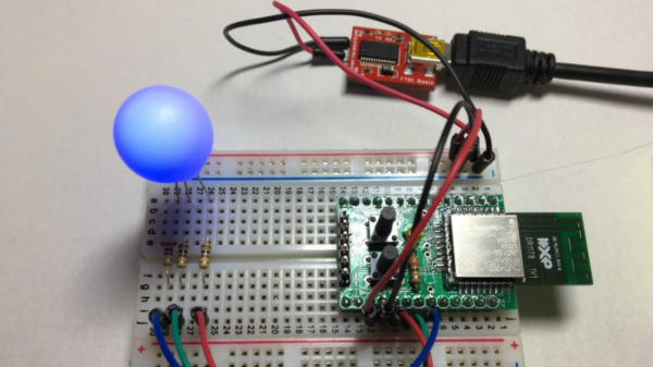
All of this work culminates in two custom firmware binaries; one for white dimmable lights and another for RGB dimmable ones. It even runs on these cheap JN5168 breakout kits he found for a few bucks. With all of the software taken care of, and having cheap ZigBee Light Link compatible modules on hand, building low cost Hue compatible lights becomes pretty straight forward.
Thanks [wind-rider] for the tip.