It’s taken longer than some might have thought, but we’re finally at the point where you can pick up an SLA 3D printer for a few hundred bucks. These machines, which use light to cure a resin, are capable of far higher resolution than their more common FDM counterparts, though they do bring along their own unique issues and annoyances. Especially on the lower end of the price spectrum.
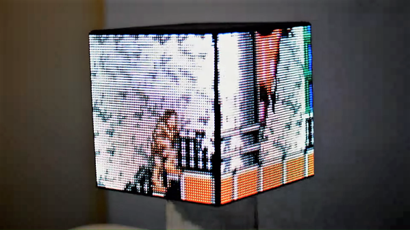
[FlorianH] recently picked up the $380 SparkMaker FHD, and while he’s happy with the printer overall, he’s identified a rather annoying design flaw. It seems that the upgraded UV backlight in the FHD version of the SparkMaker produces somewhat irregular light, which in turn manifests itself as artifacts on the final print. Due to hot spots on the panel, large objects printed on the SparkMaker show fairly obvious scarring.
Now you might expect the fix for this problem to be in the hardware, but he’s taken it in a different direction. These printers use an LCD panel to block off areas of the UV backlight, thereby controlling how much of the resin is exposed. This is technique is officially known as “masked SLA”, and is the technology used in most of these new entry level resin printers.
 As luck would have it, the SparkMaker FHD allows showing various levels of grayscale on the LCD rather than a simple binary value for each pixel. At least in theory, this allows [FlorianH] to compensate for the irregular backlight by adjusting how much the UV is attenuated by the LCD panel. He’s focusing on the printer he personally owns, but the idea should work on any masked SLA printer that accepts grayscale values.
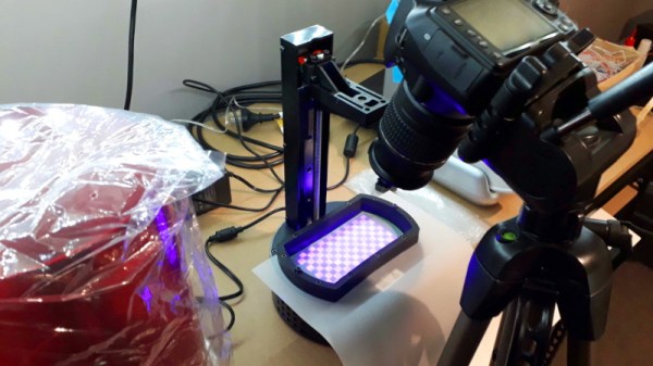
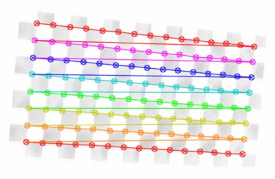
The first step was to map the backlight, which [FlorianH] did by soaking thin pieces of paper in a UV reactant chemical, and draping them over the backlight. He then photographed the illumination pattern, and came up with some OpenCV code that takes this images and uses the light intensity data to compensate for the local UV brightness underneath the sliced model.
So far, this method has allowed [FlorianH] to noticeably reduce the scarring, but he thinks it’s still possible to do better. He’s released the code for this backlight compensation script, and welcomes anyone who might wish to take a look at see how it could be improved.
An uneven backlight is just one of the potential new headaches these low-cost “masked” SLA printers give you. While they’re certainly very compelling, you should understand what you’re getting into before you pull the trigger on one.