While modern gaming systems deliver ever more realistic experiences, there’s still something to be said for the consoles and handhelds of the 80s and 90s. For many, the appeal is nostalgic. Others are attracted to the “lo-fi” graphical and sound design of these games, necessitated by the limited hardware of the time.
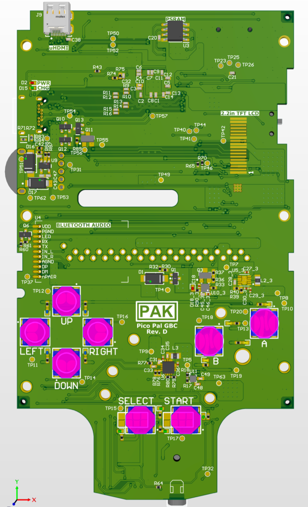
That said nobody would claim those old systems were perfect. Which is why a hybrid approach like [Peter Khouly] has been working on with the Pico Pal might be the ultimate solution. This replacement motherboard for the Game Boy Color (GBC) is powered by the RP2350, meaning the external hardware will have the same look and feel as it did back in 1998, but you’ll still be able to reap the benefits of modern emulation.
 While the origins of the project go a bit farther, [Peter] has been working on this particular variation of the Pico Pal GBC since August, and has kept a fascinating log of his progress. Just getting the RP2350 to emulate Pokémon isn’t really that big of a deal, but getting all the ancillary hardware implemented and fitted inside the case of the GBC is a different story. Especially since [Peter] intends to pack plenty of features into the final product, such as rechargable batteries, Bluetooth audio, real-time clock support, and digital video out.
The most recent status update is from just last week, where [Peter] goes over some of the new features he’s been working on. A major one is the soft power solution, where the physical power switch doesn’t just pull the plug like it did back in the 1990s. Instead, the switch triggers the board to save the game and enter into a low-power mode so that it can come right back on to where you left off. This does impact battery life, but so far, it looks like the Pico Pal GBC will be able to run for at least five hours on a charge, and more than twice that if you don’t mind turning off the audio.
It sounds like there’s still several gremlins to track down in the design, but even in its current state, the Pico Pal GBC looks very interesting. We’re immediately reminded of the phenomenal work [Bucket Mouse] has put in on a similar refit for the original DMG-1 Game Boy.