Tiptoe Through The Tulips In No Time With Ukule-LED

Take it from someone who has played at the guitar for over 20 years: reading sheet music can be a big stumbling block to musical enjoyment. Playing by ear is somewhat unreliable, tablature only works well if you’re already familiar with the tune and tempo, and pulling melody from chord charts is like weaving fiction from the dictionary. A lot can be said for knowing basic chord formations, but it can be difficult get your fingers to mimic what you see on the page, the screen, or someone else’s fretboard. Enter Ukule-LED, a learning tool and all-around cool project by [Raghav and Jeff] at Cornell.

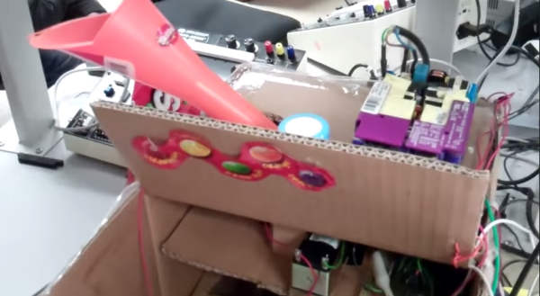
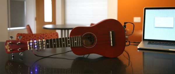
Ukule-LED uses 16 NeoPixels across the first four positions of the fretboard to teach chord positions. All 16 NeoPixels are connected in series to a single pin on an ATMega1284P, which sits on a board mounted to the bottom of the uke along with power and serial. [Raghav and Jeff] set the NeoPixels below the surface so as not to interrupt playability. The uke can operate in either of two modes, ‘play’, and ‘practice’. In ‘play’ mode, the user feeds it a text file representing a song’s chords, tempo, and time signature. The LEDs show the chord changes in real-time, like a karaoke teleprompter for fingers. In ‘practice’ mode, the user enters a chord through the CLI, and the lights hold steady until they get a new assignment. Knowing which fingers to use where is up to the user.

To add another layer of learning, major chords alight in green, minor chords in red, and 7th chords in blue. These are the currently supported chord types, but the project was built with open, highly extendable Python sorcery available for download and subsequent tinkering. Go on tour after the break.

Continue reading “Tiptoe Through The Tulips In No Time With Ukule-LED”

Taste The Rainbow One Color At A Time

It’s the end of another fall semester of Bruce Land’s ECE4760 class at Cornell, and that means a fresh crop of microcontroller-based student projects. For their project, [Alice, Jesse, and Mikhail] built a Skittle-sorting miniature factory that bags and seals same-colored candies into little pouches of flavor.

Their design is split into three stages, which are visually delineated within the all-cardboard housing. Skittles are loaded into a funnel at the top that leads to the color detection module. The color is determined here with an RGB LED and OPT101 photodiode driven by an ATMega1284.  Because the reflected RGB values of red and orange Skittles are so similar, the detector uses white light to make the final determination.

Once the matchmaking is over, a servo in the second stage rotates to the angle that corresponds with the color outcome. The Skittle then slides down a cardboard chute, passes through a hole in a cardboard disk, and drops into a hanging bag. Once the bags have reached the predetermined capacity, another servo moves the carousel of bags to a nichrome wire sealing rig. Lead factory worker [Jesse] must intervene at this point to pull the bags off the line. You can see the full walk-through and demonstration of this Skittle flavor separator after the break.

Continue reading “Taste The Rainbow One Color At A Time”

nixieclock

Simple And Elegant Single Digit Nixie Tube Clock

We’ve seen a few Nixie projects around here before, but this one might be the simplest yet. [Pinomelean] designed this simple nixie tube clock with just a handful of components.

The Nixie tube chosen for the project is an IN-12a. This tube can be purchased for around just four dollars. It is capable of displaying one digit at a time, zero through nine. Since the tube can only display one digit at a time, the clock is programmed to flash each digit of the current time one by one. There is a longer pause in between each cycle to make it easier to tell when the cycle begins and ends.

The system is broken into two main components. The first is the clock circuit. The clock runs off a PIC microcontroller with a 4MHz crystal. All of the logic is performed via the PIC and only a handful of other components are required. This includes some resistors and capacitors as well as a few high voltage SMD transistors to control the Nixie tube. [Pinomelean] has made this PCB design available so anyone can download it and make their own clock.

The second component to the clock is the power supply. The system is powered by a lithium-ion rechargeable battery, but [Pinomelean] notes that it can also be powered with USB. The lower voltage works well for the microcontroller, but the Nixie tube needs a higher voltage. [Pinomelean] built his own high voltage supply using components scavenged from an old disposable camera. This power supply board design is also made available for download, but it plugs into the main board so you can use another design if desired.. Check out the demo video below to see it in action. Continue reading “Simple And Elegant Single Digit Nixie Tube Clock”

USB On The Teensy 3 From The Ground Up

When implementing USB on a microcontroller, most people are going to reach for V-USB if they’re using an AVR, one of Microchip’s USB libraries if a PIC is involved, or any number of the USB libraries for various ARM processors. [Kevin] had a different idea. As a challenge to himself, he wrote a USB device driver for the Teensy 3.1 microcontroller board, getting as close to the bare metal as he could get.

Writing a USB device driver first required a literature review. There are a few peculiarities in the Freescale K20 family of microcontrollers – the one found in the Teensy 3.1 – that dictate the need for a specific memory layout, using several clocks, and handling all the USB descriptors. [Kevin] started with the clocks, every last one of which must be enabled. The clock is generated by the Multipurpose Clock Generator from a 16MHz crystal, PLL’ed to the frequencies the USB module needs, and sent out over the System Integration Module.

Following the flowcharts and sequences found in the Freescale reference guide told [Kevin] exactly what needed to be done with the startup sequence, and offered a few suggestions on what needed to be done to set up all the interrupts. [Kevin] spent an incredible amount of time documenting, programming, and smashing his head against the keyboard for this tutorial, but he does give everyone a great opportunity to learn from his struggles.

While [Kevin] has a mostly complete USB device driver, his work is far from done. That’s alright, because this project wasn’t meant to be a full-featured driver; it’s still missing real error handling, strings in the configuration, and a real VID/PID. That’s alright, it’s still a great exercise in building something from scratch, especially something that very few people have built successfully.

Oh, blatant Hackaday Store plug for the Teensy 3.1.

12 Mbps Communication Between A PC And MCU

The world of hobby electronics have only started putting USB in projects for the last few years, and right now, pushing 1.5 Mbps down a USB port is good enough for most cases. This isn’t true for all cases; that’s a terrible data rate, really, and to get the most out of a USB connection, you can at least move up to USB Full Speed and 12 Mbps.

[Linas] is using the STM32F4 microcontroller for this example, an extremely large and very capable chip. [Linas] is using FTDI’s FT2232D USB UART to send data from an SPI port over USB. This chip does support 12 Mbps, but only after a few additions; an external EEPROM must be connected to the FTDI chip to provide a USB 2.0 device descriptor, otherwise the connection between the microcontroller and a computer is limited to 1.5 Mbps. Even using the USB on the STM32 would be a bottleneck in this case; [Linas] is moving data out of the processor using only the DMA controller – using the USB on the STM32 would eat up processor cycles in the microcontroller.

Thanks to the DMA controller inside the STM32, the microcontroller is capable of sending and receiving data through SPI at the same time. The STM32 is capable of reading and writing to the Tx and Rx buffer at the same time, but the computer is only capable of half-duplex operation – it can only read or write at any one time. [Linas] is setting up the DMA controller on the STM32 as a circular mode, putting everything in the buffer into the FTDI chip, and reading everything sent from the computer back into the STM32’s memory. After counting off the correct number of packets. the controller resets everything, moves the circular buffer back to the beginning, and starts the whole process over again.

The circuit was prototyped with an STM Discovery board. With Labview, [Linas] can see the bits coming out of the microcontroller, and send some bits back to the micro over USB. [Linas] has an extraordinarily detailed video tutorial on this project. You can check that out below.

Continue reading “12 Mbps Communication Between A PC And MCU”

Scope Noob: Microcontroller Quirks With DDS

In this installment of Scope Noob I’m working with Direct Digital Synthesis using a microcontroller. I was pleasantly surprised by some of the quirks which I discovered during this process. Most notably, I had a chance to look at errant triggers solved by using holdoff and a few timing peculiarities introduced by my use of the microcontroller. Here’s a video synopsis but I’ll cover everything in-depth after the break.

Continue reading “Scope Noob: Microcontroller Quirks With DDS”

Frappé Coffee Robot Offers Automated PIC-Me-Up

Although [Giorgos Lazaridis] has graced Hackaday several times, we’ve never covered the build of his frappé machine which reader [Jim] encountered after searching for information about the PIC16F1937. His site shows the build as in-progress, but he definitely has a working prototype here, and it’s definitely awesome.

Frappé coffee is made by mixing spray-dried instant coffee, a small amount of cold water, and sugar to taste in a manual shaker or a milkshake machine that uses a single beater. More water and/or milk is added as desired to top off the glass. The method was invented by accident in Thessaloniki, Greece, and has become quite popular.

In addition to sixteen pages of detailed build logs, [Giorgos] shot videos that demonstrate each of the modules that make up the machine. The operator puts a glass in a holder attached to a turntable. It moves first to the coffee and sugar dispenser, which fall through the same easily removable funnel. The next stop combines the add-water-and-beat steps beautifully. A length of hose strapped to the beater’s housing dispenses the initial cold water base. Then, the beater lowers automatically to beat the mixture. After mixing, the beater is drawn back up an inch or so, and more water is dispensed to rinse it off. Then the beater is fully withdrawn and the glass is filled the rest of the way. The final stop for the frappé is essential to the process: a bendy straw must be added. This is vitally important, and [Giorgos] handles it admirably with a stinger that shoots a straw into the glass.

[Giorgos]’s coffee robot is built around a PIC16F1937. He rolled his own PCB for the motherboard and each of the machine’s modules. There is a lot of logistical ingenuity going on in this project, and [Giorgos]’ build logs convey it all very well. Be sure to check out [Giorgos]’ machine in action after the break. The full set of eight videos that shows each module and culminates in the one below is well worth your time.

Continue reading “Frappé Coffee Robot Offers Automated PIC-Me-Up”