If you want to add humidity and temperature sensors to your home automation sensor, you can — like [Maker’s Fun Duck] did — buy some generic ones for about a buck. For a dollar, you get a little square LCD with sensors and a button. You even get the battery. Can you reprogram the firmware to bend it to your will? As [Duck] shows in the video below, you can.
The device advertises some custom BLE services, but [Duck] didn’t want to use the vendor’s phone app, so he cracked the case open. Inside was a microcontroller with Bluetooth, an LCD driver, a sensor IC, and very little else.
You might wonder why [Kevin] wanted to build digital calipers when you can buy them for very little these days. But, then again, you are reading Hackaday, so we probably don’t need to explain it.
The motivation, in this case, was to learn to build the same mechanism the commercial ones use for use in precise positioning systems. We were especially happy to see that [Kevin’s] exploration took him to a Hackaday.io project which led to collaboration between him and [Mitko].
We’ve noticed that adding electronic paper displays to projects is getting easier. [NerdCave] picked up a 4.2-inch E-ink panel but found its documentation a bit lacking when it came to using the display under MicroPython. Eventually he worked it out, and was kind enough to share with the rest of the class.
These paper-like displays draw little power and can hold static images. There were examples from the vendor of how to draw some simple objects and text, but [NerdCave] wanted to do graphics. There was C code to do it, but it wasn’t clear how to port it to Python.
The key was to use the image2cpp website (we’ve used it before, but you can also use GIMP). Instead of C code, though, you get the raw bytes out and place them in your Python code. Once you know the workflow, it isn’t that hard, and this is an inexpensive way to add a different kind of display to your projects. The same image conversion will help you work with other displays, too.
How can you tell if your software is doing what it’s supposed to? Write some tests and run them every time you change anything. But what if you’re making hardware? [deqing] has your back with the Automatic Hardware Testing rig. And just as you’d expect in the software-only world, you can fire off the system every time you update the firmware in your GitHub.
A Raspberry Pi compiles the firmware in question and flashes the device under test. The cool part is the custom rig that simulates button presses and reads the resulting values out. No actual LEDs are blinked, but the test rig looks for voltages on the appropriate pins, and a test passes when the timing is between 0.95 and 1.05 seconds for the highs and lows. Firing this entire procedure off at every git check-in ensures that all the example code is working.
So far, we can only see how the test rig would work with easily simulated peripherals. If your real application involved speaking to a DAC over I2C, for instance, you’d probably want to integrate that into the test rig, but the principle would be the same.
Are any of you doing this kind of mock-up hardware testing on your projects? Is sounds like it could catch bad mistakes before they got out of the house.
When we think of an m.2 slot in our laptop or similar, it’s usually in the context of its PCI connectivity for high-speed applications such as solid state disks. It’s a connector that offers much more than that interface though, making it suitable for some unexpected add-ons. As an example [MagicWolfi] has produced an m.2 card which contains the equivalent of a Raspberry Pi Pico.
The board itself has the familiar m.2 edge connector at the bottom, and the RP2040 GPIO lines as postage-stamp indentations round the edges. On the m.2 front is uses the USB interface as well as a UART and the I2C lines, as well as some of the interfaces we’re less familiar with such as ALERT, WAKE, DISABLE1/2, LED 1/2, and VENDOR_DEFINED.
On one level this provides a handy internal microcontroller card with which you can do all the things you’d expect from a Pi Pico, but on another it provides the fascinating possibility of the Pico performing a watchdog or other function for the host device. We would be genuinely interested to hear more about the use of the m.2 slot in this way.
Generally speaking, the Hackaday Supercon badge will always have a place for SAO (rebranded as “Supercon add-ons”), and that makes sense. We did originate them, after all. This year, though, we’ve gone all in on SAO, and, in particular, we’ve asked to see more SAOs with communication capabilities. The standard has always had an I2C bus, but few people use them. I decided I wanted to set an example and cook up a badge for Supercon. Was it hard? Yes and no. I’ll share with you a little about the board’s genesis and the issues I found. At the end, I’ll make you a special offer, if you are going to Supercon.
The Idea
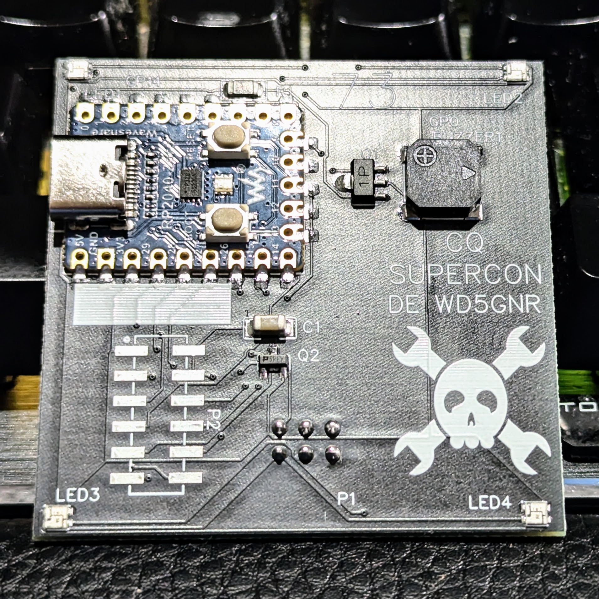
The front of the SAOGNR — the SAO connector is, of course, on the back
I’ve been a ham radio operator for a very long time. In fact, July was my 47th anniversary in the radio hobby. Well, that’s not true. It was my 47th year with a license. I had been listening to shortwave long before then. So, I wanted to do something with Morse code. You don’t have to know Morse code to get a license these days, but a lot of hams enjoy it.
I set out to do a simple board that would play some Morse code messages. But that’s just another blinking light LED with a buzzer on it, too. So, naturally, I decided it would also provide Morse code output for the I2C host. That is, the SAO could be used to convert ASCII to Morse code. Sounds simple, right? Sure.
Getting Started
I wanted to use a Raspberry Pi Pico but didn’t want to violate the SAO size requirements. Luckily, there’s an RP2040-Zero module that is quite tiny and looks more or less like a normal Pico. The two big differences are plusses: they have a reset button, and instead of a normal LED, they have a WS2812b-style LED.
[Igor] has an AS5600 magnetic rotary encoder chip on a breakout board. Normally, you’d think that was an easy device to work with since it has an I2C interface. But [Igor] wanted to do it the hard way. What’s the hard way? By hand. He directly manipulates the clock and data lines using some push buttons. You can see how it goes in the video below.
This is possible because the controlling device — in this case [Igor] — gets to set the clock rate, and there’s no reason it has to be regular. We have to admit that it never occurred to us to do this, but we have written “bit banged” I2C-like code before.