Reverse Engineering ST-Link/V2 Firmware

reverse-engineering-stlink-v2

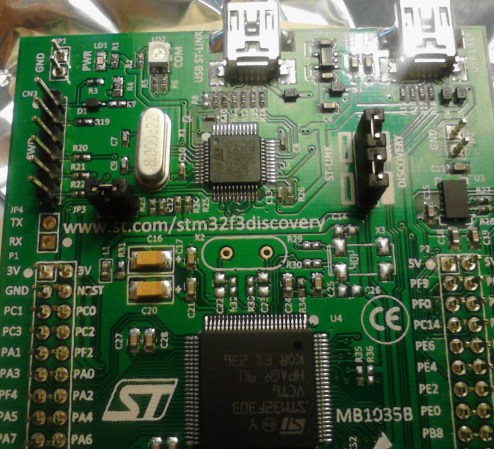
The chip seen just above the center of this image is an ARM Cortex-M3. It provides the ability to interface and program the main chip on the STM32F3 Discovery board. The protocol used is the ST-Link/V2 which has become the standard for ST Microelectronics development boards. The thing is, that big ARM chip near the bottom of the image has multiple UARTs and bridging a couple of solder points will connect it to the ST-Link hardware. [Taylor Killian] wanted to figure out if there is built-in firmware support to make this a USB-to-serial converter and his path to the solution involved reverse engineering the ST-Link/V2 firmware.

The first part of the challenge was to get his hands on a firmware image. When you download the firmware update package the image is not included as a discrete file. Instead he had to sniff the USB traffic during a firmware update. He managed to isolate the file and chase down the encryption technique which is being used. It’s a fun read to see how he did this, and we’re looking forward to learning what he can accomplish now that’s got the goods he was after.

Playing A WAV File With 64 Bytes Of RAM

montage-final

[Jacques] thought his doorbell was too loud, so of course the first thing that came to mind was replacing the electronics and playing a WAV file of his choosing every time someone came knocking. What he ended up with is a very neat circuit: he used a six-pin microcontroller with 64 bytes of RAM to play an audio file. (French, Google translation)

The microcontroller in question is a PIC10F322. one of the tiniest PICs around with enough Flash for 512 instructions, 64 bytes of RAM, and a whole bunch of other features that shouldn’t fit into a package as small as a mote of dust. Without the space to store audio data on the microcontroller, [Jacques] turned to a 64 kilobyte I2C EEPROM. The PIC communicates with the EEPROM with just two pins, allowing it to read the audio data and spit it out again via PWM to an amplifier. The code required for this feat is only 253 instructions and uses just a few bytes of RAM; an impressive display of what a very small microcontroller can do.

Estimate Velocity Using Quadrature Encoder Data

quadrature-encoder-velocity
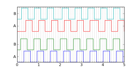
Many motors offer a quadrature encoder that give feedback on whether, and in which direction, the motor shaft is moving. But if you’re clever about analyzing the data you can use a quadrature encoder to estimate motor velocity. [Jason Sachs] makes the case that it’s fairly easy to get this wrong. Lucky for us he has carefully laid out his process of extrapolating velocity from the two edge-trigger data sources.

The process starts with reading from the encoder. Many chips have peripherals that will interface with a rotary encoder, but hardware lacking that built-in helper can still be used by monitoring pin-change interrupts. Once connected samples are taken over time and the rest is left to the quality of your algorithm.

What can this velocity data be used for? That’s up to you. But we can think of a couple of projects. It may be useful in a spinning POV display like this FPGA-based beauty. You also find quadrature encoders in exercise equipment. Knowing the velocity will help if you’re building your own computer to replace what came with that Stairmaster.

[via Reddit]

Accurate Timers With An AVR

timer

An awful lot of microcontroller projects use timers to repeat an action every few minutes, hours, or days. While these timers can be as accurate as a cheap digital wrist watch, there are times when you need a microcontroller’s timer to measure exactly, losing no more than a few milliseconds a day. It’s not very hard to get a timer to this level as accuracy, as [Karl] shows us in a tutorial.

The problem with keeping time with a microcontroller has to do with the crystal, clock frequency, and hardware prescalers of your chip of choice. [Karl] started his project with an ATMega168 and a 20 MHz crystal and the prescaler set at 256. This made the 78.125 interrupts per second, but the lack of floating point arithmetic means one second for the microcontroller will be 0.9984 seconds to you and me.

[Karl]’s solution to this problem was to have the ATMega count out 78 interrupts per second for seven seconds, then count out 79 interrupts for one second. It’s not terribly complicated, and now [Karl]’s timers are as accurate as the crystal used for the ‘168’s clock.

Morse Code Flower Is Trying To Tell You Something

morse-code-flower

To the casual observer this flower looks nice as its illuminated center fades in and out. But there’s hidden meaning to that light. Some of the blinks are longer than others; this flower is using Morse Code.

[Renaud Schleck] wanted to try a few different things with his MSP430 microcontroller. He decided on an LED that looks like a flower as it will be a nice piece of decor to set around the home. To add the Morse Code message he wanted something a bit more eloquent (and less distracting) than purely digital flashing. So he took the dots and dashes of the hard-coded message and turned them into fading signals by using Pulse-Width Modulation.

He free-formed the circuit so that it, and the coin cell that powers it, would fit in the flower pot. A reed switch is responsible for turning the juice on and off. When placed near a magnet the flower begins its gentle playback.

Continue reading “Morse Code Flower Is Trying To Tell You Something”

Three Conceptual Approaches To Driving A WS2811 LED Pixel

driving-a-ws2811

[Cunning_Fellow] published a post with three proof-of-concept approaches to driving a WS2811 LED pixel. We looked at a project early in December that used an AVR microcontroller to drive the RGB package. [Cunning_Fellow] saw this, and even though he doesn’t have any of these parts on hand he still spent the time hammering out ways to overcome the timing issues involved with address the device. His motto is “put up or shut up” when it comes to criticizing projects featured on Hackaday. We love seeing someone pick up an idea and run with it.

The approach in all three cases aims to conserve clock cycles when timing the communications. This leaves the developer as many cycles as possible to perform other tasks than simply telling the lights what to do. One approach is an assembly routine that is just a shade slower but groups all 14 free cycles into one block. The next looks at using external 7400 series hardware. The final technique is good old-fashioned bit banging.

[Photo Credit]

Overclocking Microcontrollers

We’re all familiar with overclocking desktop computers; a wonderful introduction to thermal design power and the necessities of a good CPU cooler. [Marcelo] wanted to see how far he could overclock a microcontroller – in this case an ATMega328 – and ended up with a microcontroller designed for 20 MHz running at 30 MHz.

To verify that his uC could run at higher clock speeds, [Marcelo] began his experiments by uploading a piece of code that toggled a few pins as fast as possible. He needed to upload this code with a common 16 MHz crystal – AVRDude simply won’t work when a chip is clocked at higher speeds.

After successfully demonstrating his microcontroller will turn pins on and off at 30 MHz, [Marcelo] wanted to see if he could do something useful. By editing a single setting in his Arduino boards.txt file., [Marcelo] was able to have his overclocked microcontroller read and reply to characters sent over a serial connection. It worked, demonstrating an overclocked microcontroller could be useful in some situations.

As for what [Marcelo] plans to do with his faster microcontroller, he’s thinking of improving a ATMega-powered VGA color generator. A higher clock speed means he can push more pixels out to a VGA monitor.