AVR VGA Generator

avr-vga-generator

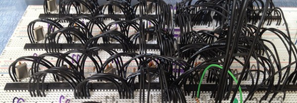
This simple circuitry makes up the hardware for [Andrew’s] AVR-based VGA generator. He managed to get an ATmega1284 to output a stable VGA signal. Anyone who’s looked into the VGA standard will know that this is quite an accomplishment. That’s because VGA is all about timing, and that presented him with a problem almost immediately.

The chip is meant to run at a top speed of 20 MHz. [Andrew] did manage to get code written that implemented the horizontal and vertical sync at this speed. But there weren’t enough clock cycles left to deal with frame buffering. His solution was to overclock the chip to 25 MHz. We assume he chose that because he had a crystal on hand, because we think it would have been easier to use a 25.174 MHz crystal which is one of the speeds listed in the specification.

Red, green, and blue each get their own two-bit range selected via a set of resistors for a total of 64 colors. As you can see in the video after the break, the 128×96 pixel video is up and running. [Andrew] plans to enlarge the scope of the project from here to make it more versatile than just showing standard images. The code (written in assembly) is available at his GitHub repository.

Continue reading “AVR VGA Generator”

Reverse Engineering Challenge Starts Off Simple

img_20130326_102537

We love seeing hard-core firmware reverse engineering projects, but the number of hackers who can pull those off is relatively small. It’s possible to grow the ranks of the hacker elite though. A hackerspace is a great place to have a little challenge like this one. [Nicolas Oberli] put together a capture the flag game that requires the contestants to reverse engineer Teensy 3.0 firmware.

He developed this piece of hardware for the Insomni’hack 2013 event. It uses the Teensy 3.0 capacitive touch capabilities to form a nine-digit keypad with a character LCD screen for feedback. When the correct code is entered the screen will display instructions on how to retrieve the ‘flag’.

To the right you can see the disassembly of the .elf file generated by the Arduino IDE. This is what [Nicolas] gave to the contestants, which gets them past the barrier of figuring out how to dump the code from the chip itself. But it does get them thinking in assembly and eventually leads to figuring out what the secret code is for the device. This may be just enough of a shove in the right direction that one needs to get elbow deep into picking apart embedded hardware as a hobby.

Continue reading “Reverse Engineering Challenge Starts Off Simple”

Making It Easier To Build Firmware

OSHW Logo

Most microcontroller manufacturers give you some kind of free development toolchain or IDE with their silicon products. Often it’s crippled, closed source, and a large download. This is pretty inconvenient when you want to have firmware that’s easy to build and distribute. I’ve found many of these toolchains to be annoying to use, and requiring closed source software to build open source firmware seems less than desirable.

It’s possible to build code for most microcontrollers using command line tools. You’ll need a compiler, the device manufacturer’s libraries and header files, and some method of flashing the device. A lot of these tools are open source, which lets you have an open source toolchain that builds your project.

Setting up these tools can be a bit tricky, so I’m building a set of templates to make it easier. Each template has instructions on setting up the toolchain, a Makefile to build the firmware, and sample code to get up and running quickly. It’s all public domain, so you can use it for whatever you’d like.

Currently there’s support for AVR, MSP430, Stellaris ARM, and STM32L1. More devices are in the works, and suggestions are welcome. Hopefully this helps people get started building firmware that’s easy to build and distribute with projects.

ATtiny2313 Frequency Meter Measures 1Hz-10MHz

attiny2313_frequency_meter

This frequency meter project squeezes a lot of performance out of the ATtiny2313 microcontroller. That chip does all of the work, measuring the frequency on the input pin as well as multiplexing the set of 7 seven-segment displays which read out the measurement.

The system is only as accurate as the clock crystal used by the AVR chip, so [Manekinen] recommends using one with the best tolerances available. It is also necessary to choose a value which is divisible by 1024 to get the best combination of accuracy and resolution. In this case he’s using a 22.1184 MHz crystal oscillator which is a slight overclocking of the chip which is spec’d to run at 20 MHz max.

We didn’t totally follow his explanation of how the two timers are used for counting. But if we really wanted to drill down for a full understanding his code (written in BASCOM-AVR) is available. If you’re just interested in the hardware we embedded a screenshot of the schematic after the break.

Continue reading “ATtiny2313 Frequency Meter Measures 1Hz-10MHz”

Fabricating Custom Displays For A Commercial Coffee Roaster

custom-display-panel-for-a-coffee-roaster

Roasting the perfect coffee bean is an art form. But even the most talented of roasters can use a little feedback on what’s going on with their equipment. [Ludzinc] recently helped out a friend of his by building this set of 7-segment displays to show what’s happening with this coffee roaster.

The yellow modules hiding underneath the display panel are responsible for setting the speed of the hot air blower and the rate at which the drum turns. They’re adjustable using some trimpots, but it sounds like the stock machine doesn’t give any type of speed feedback other than direct observation.

The solution was to patch into those speed controllers using the ADC of a PIC chip. They each output 0-10V, which [Ludzinc] measures via a voltage divider. After the speed is quantified the microcontroller outputs to one of the displays. Since there’s a different chip for each readout, the firmware can be custom tuned to suit the operator’s needs.

Keep this in mind if you’re still planning to build that coffee roaster out of a washing machine.

Script Makes Custom Pinout Labels For Your Chips

cusom-pinout-labels

After years of prototyping hobby electronics we’ve learned (several times actually) that when something’s not working it’s a problem with the hardware. Usually the jumper wires aren’t hooked up correctly, or we needed to throw a pull-up resistor in and forgot to. One thing that can really help sort these problems out quickly is a pinout label for each chip like the ones seen above. This is a project which [John Meacham] came up with. It uses a script to generate chip pinouts on a label maker.

The label maker he started with is a Brother PT-1230PC. It connects to a computer via USB and can use a few different widths of self adhesive label tape. [John] found that the 1/4″ wide tape is nearly a perfect fit for PDIP components.

His script takes a YAML file as the input. This formatting standard makes is quick an easy to whip up a label for a new chip using just your text editor. From there his Pearl script turns the data into a Portable Network Graphics (.png) file with the labels spaced for the 0.1″ pitch of the chip. Send this graphic to your label maker and you’ve got an adhesive reminder that will help reduce the time you spend pawing through datasheets just for the pinouts.

Enabling An Unused Touchscreen Overlay On A Consumer LCD

uncovering-an-unused-touchscreen-on-a-consumer-lcd

When [Andrei] first got his Raspberry Pi he wanted to make it a standalone computer right away. This means the normal input devices like a mouse and keyboard, but also some type of display. To avoid waiting for shipping he ended up using a cheap vehicle backup camera screen from the local big box store. It worked great, and recently he decided he would try to convert it to run off of 5V power to simplify his setup. While snooping around inside the device he discovered an unused resistive touch overlay and figured out how to get it to work.

What tipped him off is the small four-conductor connector which wasn’t hooked up to anything. He carefully soldered wires onto the flexible circuit traces, then generously covered them in hot glue to help prevent movement from breaking the rigid connection. To get this working you need to measure the resistance between the conductors. Most of the time we figure the RPi GPIO header can be used directly, but for this task an intermediary is necessary. [Andrei] went with a small Arduino clone board. A bit of trial and error was all it took to get the connections right and to iron out the code which translates the values into coordinates.