Echo Box Shakes Itself To Make Sound

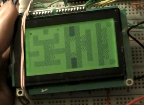
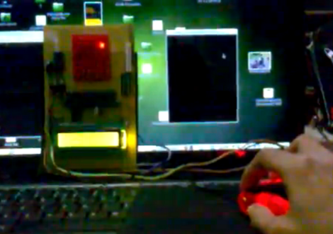
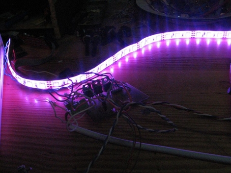
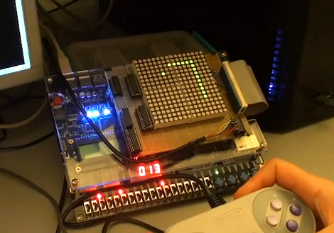
The echo box performs exactly as its name implies. If you tap out a rhythm on the lid, it will tap the same thing back to you. Except it isn’t tapping to make the sound, but vibrating.

The concept is similar to the Knock Block. In that hack, a piezo element detected a rapping on the wooden enclosure and repeated the rhythm by striking the lid with a solenoid. This iteration also uses a piezo element as the sensor. In the image above you can see a segment of PVC pipe in the upper corner. That houses the element, sandwiched between two pieces of wine bottle cork. That cork just touches the lid of the box, transferring the vibrations to the element.

The sound is created by a motor with an offset weight on its spindle. When the motor spins, it causes vibrations. The enclosure is one wood box inside of another, so the vibrating motor cause the inner box to shake against the outer one to make noise. Hear it for yourself in the clip after the break.

Continue reading “Echo Box Shakes Itself To Make Sound”

AVR External Memory Interface (XMEM) Reads Input Matrix

Reading from a large number of inputs, like this piano keyboard, can be tedious. Even when multiplexing there’s a lot to keep track of. But if you choose the right microcontroller, you may have hardware assistance. Here’s an ATmega640 is using it’s external memory interface to read the key matrix.

You may remember the Open Music Labs article about reading from a shift register using just one pin of a microcontroller. This time around a shift register is still used, but instead of pulling in a long line of parallel inputs, the switches are multiplexed to reduce the number of I/O pins used to read them.

A 74HC573 is used to facilitate the multiplexing. We won’t go into how that part is accomplished; there’s a separate post that explains the process. What’s unique here is that the XMEM peripheral of the AVR microcontroller is used to grab the data. This is intended for external memory chips, but if you get the timing just right, it greatly simplifies reading in a matrix of up to 128 inputs.

Binary Division When Your Processor Lacks Hardware Division

[Hamster] wanted to take a look at division operations when the chip you’re using doesn’t have a divide instruction. He makes the point that the divide instruction takes a lot of space on the die, and that’s why it’s sometimes excluded from a chip’s instruction set. For instance, he tells us the ARM processor used on the Raspberry Pi doesn’t have a divide instruction.

Without hardware division you’re left to implement a binary division algorithm. Eventually [Hamster] plans to do this in an FPGA, but started researching the project by comparing division algorithms in C on an AMD processor.

His test uses all 16-bit possibilities for dividend and divisor. He was shocked to find that binary division doesn’t take much longer than using the hardware instruction for the same tests. A bit of poking around in his code and he manages to beat the AMD hardware divide instruciton by 175%. When testing with an Intel chip the hardware beats his code by about 62%.

He’s got some theories on why he’s seeing these performance differences which we’ll let you check out on your own.

Lamp Fading And Remote Control For The Lazy

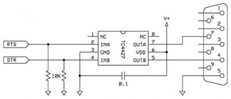
[Dmitry Grinberg] has to walk all the way across his bedroom to switch the lamp on and off. The drudgery of this finally became too much, so he built a remote control and added dimming for good measure. Above you can see the circuitry for the remote and the receiver, as well as the finished remote housed in what he calls a ‘Chinese Altoids tin’.

After the break you’ll find [Dmitry’s] demo video. The remote control is quite responsive, and the dimming has great resolution. That’s thanks to a power N-channel MOSFET which switches the AC with the help of a full wave rectifier. The PIC 12F617 that controls the MOSFET is powered separately, and [Dmitry] mentions that you must use a transformer and not a switch-mode power supply to avoid a fire. We’d like to know more about this, so leave a comment if you are able to explain further.

The remote and receiver communicate via Infrared. The protocol is operating with 38 kHz signals using an easily sourced receiver tuned to that frequency. [Dmitry] shares all the details about the encoding scheme that he uses. Recreating this communications pairing is a great way to test your understanding of this technique. But if you need a refresher, here’s a tutorial to push you in the right direction. Continue reading “Lamp Fading And Remote Control For The Lazy”

Adding Sound And Light To Your Radio Controlled Vehicles

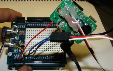
[Nicholas] wanted to add some flair to his RC car. In addition to the headlights that you see above, there’s brake lights, and a horn that plays “Dixie” like the General Lee in the Dukes of Hazard. All of this is triggered by the wireless controller, but he figured out a way to monitor the servo signals in order to add the additional features.

The hack is driven by a Propeller chip. [Nicholas] patches into the servo lines by adding a servo-in and servo-out header to his prototyping shield. With that in place he’s able to tap into the voltage and ground pins to power the microcontroller. By attaching a 4k7 resistor to the control line, he can listen in on the servo signals using the Propeller.

This RC car has a throttle servo. So when the throttle is opened all the way up the Propeller chip flashes some white LEDs in the headlights, and uses an LM386 audio amplifier to play a tune. When the throttle is pulled all the way back the brake lights are activated. Don’t miss the test footage of this which is embedded after the break.

Continue reading “Adding Sound And Light To Your Radio Controlled Vehicles”

ANT+ Networks Using An MSP430 Chip And Android Phone

[Jbremnant] wanted to try his hand with ANT+ wireless networks. This protocol is designed for light-weight and low-power consumer electronics, like heart rate chest straps and bicycle computers (Garmin brand devices for example). There are already libraries out there for Arduino, but [Jbremnant] found that most of them were written as slave-only code. He set out to use an MSP430 to drive a fully functioning ANT network including a computer and an Android phone.

The TI Launchpad is used as the master node in the network. [Jbremnant] chose the smaller of the two MSP430 processors that came with the dev platform. After starting down this road he realized that chip didn’t have a hardware UART needed to communicate with the SparkFun ANT board (based on the nRF24AP1 radio chip). Rolling with the punches, he used a software UART he had previously worked with. Now he’s able to transmit test data from the Launchpad. It is picked up by both a USB dongle on his computer and the Android phone seen above. Check out his demo video after the break.

Continue reading “ANT+ Networks Using An MSP430 Chip And Android Phone”

ARM Programming Primer; Getting The USART Running

We find it interesting that PIC and AVR programming is very common in hobby electronics but ARM doesn’t have nearly the same foothold. This is partly because there’s a knowledge barrier involved with making the transition (the other part is probably the lack of DIP packaged chips). But if you’ve worked with 8-bit microcontrollers you can certainly make the jump into the 32-bit realm. Here’s a great opportunity to get your feet wet. This guide will show you how to get the USART on an STM32 Discovery Board working, which makes it easy to get feedback about what’s going on in your program.

One difference you’ll notice when moving to ARM microcontrollers is that there is almost always a library bundle available from the manufacturer which includes all of the functions you need for hardware control (USART, USB, Ethernet, ADC, etc.). That’s the case here, so simply including the USART library makes it a snap to finish the rest of the program. Once you hook up your communications hardware (an FTDI cable in this case) just use the library initialization functions, followed by the send and receive commands and you’ll be pushing messages to a computer terminal in no time.

If you’re trying to use the STM32 Discovery Board with a Linux box here’s a shove in the right direction.