MSP430-based Wristwatch Project

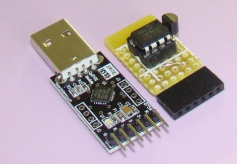
[Nav] is working on a scratch-built wristwatch. Although it is based on an MSP430 microcontroller, it’s not the ready-to-hack ezCronos that you might be thinking of. Instead, [Nav] started with a different TI development tool that we’ve looked at before, the ez430-F2013.

The breakout board for the F2013 is small enough to meet his needs, but still provides easy soldering with 0.1″ vias that break out each pin. To make sure the timepiece is accurate he added a 32.768 kHz clock crystal. A small, square, LCD screen acts as the face of the watch, but we didn’t find specific part information for the display.

Currently the watch can run for a few days on the CR2032. We’d bet some work with sleep modes for the microcontroller can help with that. The watch has a couple of buttons that let you control it, and [Nav] discovered that he could fit everything into the watch case for an iPod nano. That’s creative!

We’ve seen other hacks with tiny batteries. The next logical step here would be to swap out the disposable coin cell for something that can be topped off with an external charger.

Running The Linux Kernel On A DE0-nano FPGA Board

[Mike] has been filling up a rather intense wiki entry outlining how to run uClinux on a DE0-nano FPGA board. This is an inexpensive dev board that will run you somewhere between $80 and $100. Right off the bat he goes into a hefty list of the reasons that this is a foolish activity. To name a few: Once you’ve complete the build the device will be tethered for reboot.  This board doesn’t have Ethernet hardware and TCP/IP is one of the beast features of the uClinux kernel. And the FPGA tools are closed-source, which doesn’t often mesh with the ideals of Linux developers. But we still like to see what it really takes to get these large-scope firmware builds to compile and load correctly.

After his preamble you’ll find three main chunks. The first deals with setting up the toolchain on Fedora 14. From there, he installs packages necessary for cross-compiling, pulls down the source packages, and gets to work. Once the kernel is compiled and running on the FPGA [Mike] goes on to show you how to build out a simple hardware add-on in the form of a couple of LEDs connected to extra FPGA pins. The final portion of the wiki details rolling support for toggling the LEDs into the software distribution.

Two Dice, One 8-pin UC

[Mike Shegedin] makes full use of an 8-pin microcontroller with this ATtiny13-based dice project. With a maximum of six I/O pins (that includes using the reset pin as I/O) he needed a couple of tricks in order to drive 14 LEDs and use a momentary push button for user input. We’re certainly familiar with the concepts here, but it still took quite a while to figure out what is going on with the schematic that [Mike] posted.

You’ve probably already guessed that he’s using Charlieplexing to drive more LEDs than he has pins. But when we started looking at the layout we thought he had drawn the schematic wrong, because there are six pairs of LEDs where the two diodes in each pair a not reverse biased, but hooked up in parallel. That, plus the fact that his battery is hooked up backwards. After several minutes of study the light bulb finally clicked on. Dice add pips (the dots on each side of a die) in pairs with the exception of the center pip. That means that you only need to control four total lines for each die (three pairs plus the center pip). There’s two ways to handle this, you could use four rows and two columns with traditional multiplexing, or you can reverse bias the two sets of LEDs for each die and use Charlieplexing. The former is a bit easier to program, the latter saves you one I/O pin and meant that [Mike] didn’t need to use the reset pin as I/O.

This is a clever addition to the collection of dice projects we’ve seen like the battery-less die, and the ATtiny2313 powered dice.

Building A Battery-powered Motion Alarm

[Brad] was asked by his Sister to design a motion-based alarm that would help her catch her son sneaking out of the house at night. Obviously this didn’t need to be a long-term installation so he decided to throw something together that is only active at night and can be battery-powered. What he came up with is a light-sensitive motion sensor that uses very little power.

He knew that an Arduino would be overkill, and decided to try his hand at using the Arduino to develop code for an ATtiny85. It has an external interrupt pin connected to the output of the PIR module, which triggers action when motion is detected. The first thing it does is to check the photoresistor via the ADC. If light levels are low enough, the buzzer will be sounded. [Brad] measured the current consumption of his circuit and was not happy to find it draws about 2.5 mA at idle. He spent some time teaching himself about the sleep functions of the AVR chips and was able reduce that to about 500-600 uA when in sleep mode. Now all he has to do is find a nice place behind the house to mount the alarm and there’ll be no more sneaking around at night.

If you’re trying to keep a tight leash on your own kids you could always make them punch the time clock.

Python On A Microcontroller

The team at LeafLabs was looking for something cool to do with their new ARM development board. [AJ] asked if anyone had ever played around with Python, so [Dave] cooked up an implementation of PyMite and put it on a Maple board. While the writeup is only about blinking a LED with a microcontroller, they’re doing it with Python, interactively, and at runtime.

The build uses the Maple Native board the team is developing. The board has a 32-bit ARM chip with 1 Meg of RAM – more than enough horsepower to run PyMite. The tutorial for putting PyMite on a Maple is up on the LeafLabs wiki.

PyMite is theoretically able to control every pin on the Maple Native and do just about everything a regular Python distro can do. The LeafLabs team is still working on the necessary libraries for their board (although we don’t see anything on the Google code page), so right now only blinking the LED is supported. Still, it’s pretty cool to have Python in your pocket.

Barebones PIC RFID Tag

An inductor and 8-pin microcontroller are all that make up this barebones RFID tag. You might have done a double-take when first seeing the image above. After all, there’s nothing hooked up to the power and ground pins on the chip. As [Ramiro Pareja] explains in his post, the power is actually supplied via the I/O pins to which the inductor is soldered. It seems that each I/O pin has a parasite capacitor and a pair of clamping diodes inside the chip. When the AC current that is induced by the magnetic field of the RFID reader hits those pins, the capacitors charge and the clamping diodes form a bridge rectifier. This results in power being injected into the chip, which turns around and sends the RFID code back through the inductor.

This isn’t the first time that we’ve seen this concept. We featured a hack that is exactly the same except it used an AVR chip. This one uses a PIC 12F683 but should work with just about any 12F or 16F model. The code is written in Assembly and shouldn’t need any changes for different hardware. [Ramiro] does talk a bit about adding a decoupling capacitor to Vss and Vdd, as well as a tuning capacitor to the two I/O pins used above to help make the device a little more robust. But, as you can see in the video after the break, it works just fine without them.

Continue reading “Barebones PIC RFID Tag”

ATtiny Hacks: ATtiny45/85 Servo Library

ATtiny Hacks Theme Banner

Servo8bit is a library for AVR microcontrollers that allows you to drive servo motors without the need for a 16-bit timer. Obviously, this is quite useful for smaller chips that only have 8-bit timers and it is specifically targeted at the ATtiny45 and ATtiny85 microcontrollers. The library offers 256 steps of resolution, and can drive up to five servos at one time. Servo control pulses can be generated between 512 and 2560 microseconds and if you don’t mind increasing the time between these pulses [Liya] says it would be possible to increase the 5-servo limit.

The library is quite easy to use, but in its current state it would take just a bit of work to port to another device. It’s been written for an 8 Mhz clock signal with PortB used to drive the motors. Using find-and-replace to change the PORTB keywords to use a DEFINE variable should be easy enough, but we don’t know how hard it would be to change the clock frequency.

We wonder if it’s possible to make this a slave device, perhaps implementing a 1-wire protocol?