Operating systems! They’re everywhere these days, from your smart TV to your smartphone. And even in your microcontrollers! Enter BreadboardOS for the Raspberry Pi Pico.
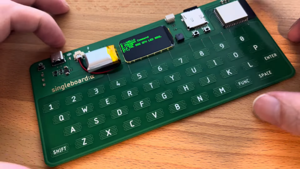
 BreadboardOS is built on top of FreeRTOS. It’s aim is to enable quick prototyping with the Pi Pico. Don’t confuse operating system with a graphical environment — BreadboardOS is command-line based. You’d typically interface with it via a serial terminal emulator, but joy of joys, it does support color!
Using BreadboardOS is a little different than typical microcontroller development. Creating an application involves adding a “service” which is basically a task in FreeRTOS parlance. The OS handles running your service for you. Via the text interface, you can query running services, and start or kill them at will.
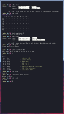
Meanwhile, running df will happily give you stats on the flash usage of the Pi Pico, and free will tell you how full the memory is doing. If you really want to get raw, you can make calls to control GPIO pins, the SPI hardware, or other peripherals, and do it right on the command line.
BreadboardOS isn’t for everyone, but it could prove a useful tool if you like that way of doing things. It’s not the only OS out there for the Pi Pico, either!
Continue reading “BreadboardOS, A Command Line Interface For The Pico”