[Sjaak], in electronic hobbyist tradition, started to design a PCB business card. However, he quickly became disillusioned with the coloring options made available by the standard PCB manufacturing process. While most learn to work with a limited color palette, [Sjaak] had another idea. PCB decals for full-color control.
As [Sjaak] realized early in his PCB journey, the downside of all PCB business cards (and PCBs in general) is the limited number of colors you can use which are dictated by the layers you have to work with: FR4, soldermask, silkscreen and bare copper. Some people get crafty, creating new color combinations by stacking layers for hues, but even that technique doesn’t come close to a full palette.
The commercial off-the-shelf out of the box solution [Sjaak] found was decal slide paper. For those of you not prone to candle making or car decorating, decals are printable plastic film that can be used to decorate ceramics, glass or other smooth surfaces. Both clear and white versions can be found in most hobby stores. Once obtained, an inkjet or laser printer can print directly onto the photo paper-like material, lending the decals an infinite range of colors.
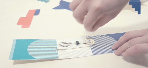
[Sjaak] bought clear film and designed his PCB with black soldermask and white silkscreen. Once the PCBs had come in, [Sjaak] got to work applying the decals with a transfer method by placing one into water, waiting a bit until the decal lets loose and then are carefully applied to a PCB. [Sjaak] reports that the process is a bit trickery because the film is very thin and is easily crinkled. But, difficulties overcome, the PCB then needs to dry for twenty-four hours. From there, it’s into the oven for 10 minutes at 248 degrees Fahrenheit (120 degrees Celsius) followed by an optional clear coating. Although the process is a bit involved, judging from his pictures we think the results are worth it, producing something that would stand out; which, in the end, is the goal of a PCB business card.
With all this in mind, we think that the logical progression is to incorporate digital logic or go full DIY and CNC or laser engrave your own business card.
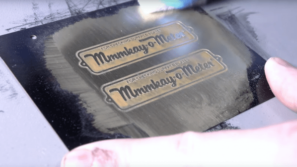
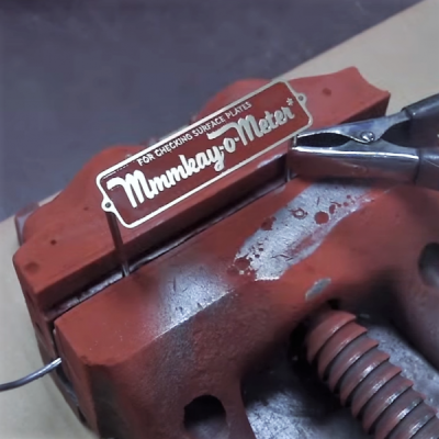 The ‘easy’ part of this only comes if you have access to a machine shop like [John] at NYC CNC does. To be fair, the only key machine for making these plates is a laser cutter, and even a guy like [John] needed to farm that out. The process is very straightforward — a brass plate is cleaned and coated with lacquer, which is then removed by the laser in the areas that are to be etched. The plate is dipped in an electrolyte solution for etching, cleaned, and powder coated. After curing the powder coat with a heat gun rather than an oven — a tip worth the price of admission by itself — the paint is sanded off the raised areas, the metal is polished, and a clear coat applied to protect the badge.