Don’t feel bad if you don’t know what Cistercian numbers are. Unless you’re a monk of the Order of Cistercia, there’s really no reason for you to learn the cipher that stretches back to the 13th-century. But then again, there’s no reason not to use the number system to make this medieval-cool computer number pad.
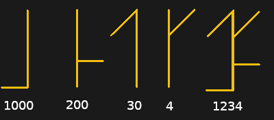
If you haven’t been introduced to the Cistercian number system, it’s actually pretty clever. There are several forms of it, but the vertical form used here by [Tauno Erik] is based on a vertical stave with nine glyphs that can be attached to or adjacent to it. Each glyph stands for one of the nine numerals — one through nine only; there’s no need for a zero glyph. There are four quadrants around the stave — upper right, upper left, lower right, and lower left — and where the glyph lies determines the multiplier for the glyph. So, if you wanted to write the number “1234”, you’d overlay the following glyphs into a single symbol as shown.
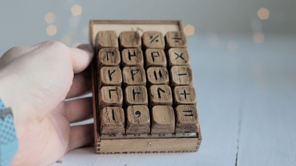
[Tauno]’s Cistercian keypad, admittedly more of an art and history piece than a useful peripheral, somehow manages to look like it might have been on the desk of [Theodoric of York, Medieval Accountant]. Its case is laser-cut birch plywood, containing a custom PCB for the 20 keyboard switches and the Xiao RP2040 MCU that runs the show. Keycaps are custom made from what looks like oak combined with a 3D-printed part, similar to his previous wooden keycap macro pad. Each of the nine Cistercian glyphs is hand-carved into the keycaps, plus an imaginary glyph for zero, which wasn’t part of the system, as well as operators and symbols that might have baffled the medieval monks.
The native Cistercian system is limited to numbers between 1 and 9,999, so we’ll guess that the keypad just outputs the Arabic numeral corresponding to the Cistercian key pressed and doesn’t actually compose full Cistercian numbers. But the code to do that would be pretty easy, and the results pretty cool, if a bit confusing for users. Even if it’s just for looks, it’s still a cool project, and we doff the hood of our monkish robe to [Tauno] for this one.