Let Slip The Chips Of War

We’re going to go out on a limb and predict that future history books will note that the decision to invade a sovereign nation straight after a worldwide pandemic wasn’t exactly the best timing. Turns out the global electronics shortage the pandemic helped to catalyze isn’t just affecting those of us with peaceful intentions, as the Russian war machine is having a few supply issues with the parts needed to build modern weapons and their associated control equipment.

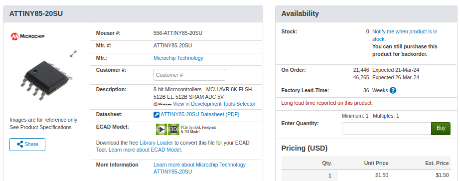
As you might expect, many of these parts are electronic in nature, and in some cases they come from the same suppliers folks like us use daily. This article from POLITICO includes an embedded spreadsheet, broken down by urgency, complete with part numbers, manufacturers, and even the price Moscow expects to pay!

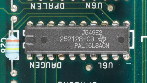
Chips from US-based firms such as Texas Instruments are particularly hard for the Kremlin to source.

So what parts are we talking about anyway? The cheapest chip on the top priority list is the Marvell ‘Alaska’ 88E1322 which is a dual Gigabit Ethernet PHY costing a mere $7.10 USD according to Moscow. The most expensive is the 10M04DCF256I7G, which is an Altera (now Intel) Max-10 series FPGA, at $1,101 USD (or 66,815 Rubles, for those keeping score).

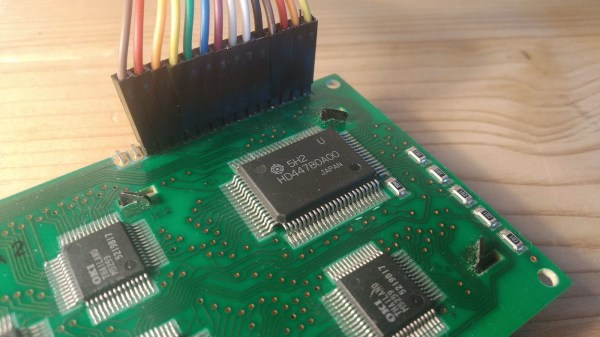
But it’s not just chips that are troubling them, mil-spec D-sub connectors by Airborn are unobtainable, as are all classes of basic passive parts, resistors, diodes, discrete transistors. Capacitors are especially problematic (aren’t they always). A whole slew of Analog Devices chips, as well as many from Maxim, Micrel and others. Even tiny logic chips from Nexperia.

Of course, part of this is by design. Tightened sanctions prevent Russia from purchasing many of these parts directly, which is intended to make continued aggression as economically unpleasant as possible. But as the POLITICO article points out, it’s difficult to prevent some intermediaries from ‘helping out’ without the West knowing. After all, once a part hits the general market, it is next to impossible to guarantee where it will eventually get soldered down.

Thanks to [Kim Tae] for the tip!

With A Little Heat, Printed Parts Handle Vacuum Duty

We don’t have to tell the average Hackaday reader that desktop 3D printing has been transformative for our community, but what might not be as obvious is the impact the technology has had on the scientific community. As explained in Thermal Post-Processing of 3D Printed Polypropylene Parts for
Vacuum Systems
by [Pierce Mayville], [Aliaksei Petsiuk], and [Joshua Pearce]
, the use of printed plastic parts, especially when based on open source designs, can lead to huge cost reductions in the production of scientific hardware.

More specifically, the authors wanted to examine the use of 3D printing components to be used in a vacuum. Parts produced with filament-based printers tend to be porous, and as such, are not suitable for fittings or adapters which need to be pumped down to below one atmosphere. The paper goes on to explain that there are coatings that can be used to seal the printed parts, but that they can outgas at negative pressures.

The solution proposed by the team is exceptionally simple: after printing their desired parts in polypropylene on a Lulzbot Taz 6, they simply hit them with a standard consumer heat gun. With the temperature set at ~400 °C, it took a little under a minute for the surface of take on a glossy appearance — the result reminds us of an ABS print smoothed with acetone vapor.

As the part is heated, the surface texture visibly changes. The smoothed parts performed far better in vacuum testing.

In addition to the heat treatment, the team also experimented with increasing degrees of infill overlap in the slicer settings. The end result is that parts printed with a high overlap and then heat treated were able to reliably handle pressures as low as 0.4 mTorr. While the paper admits that manually cooking your printed parts with a heat gun isn’t exactly the ideal solution for producing vacuum-capable components, it’s certainly a promising start and deserves further study.

Ultra-Thin Rubber Parts Made With A 3D Printed Plug

We generally think of 3D printed components as being hard bits of plastic, because for the most part, that’s what we’ve got loaded up in our desktop machines. But outside of the normal PLA, PETG, and ABS, you can also print with various flexible filaments such as TPU. This can be handy for producing custom seals, or rugged enclosures.

But what if you want to make very thin rubberized parts? In that case, the 0.4 mm nozzle on most desktop machines will be your limiting factor. But not so with the method [Daniel Bauen] demonstrates in his latest Engineerable video. The trick here is that the printer isn’t producing the final product — it’s making a water-soluble plug that has been slightly undersized for the application at hand.

Once the plug has been printed, [Daniel] sprays it with several coats of Plasti Dip. This builds up a rubberized coating on the printed part, and once it’s reached the desired thickness, the whole thing gets tossed into an ultrasonic cleaner to break up the filament. What you’re left with is a silicone-like part that has the same shape as your original print, but is far thinner than anything you could have extruded normally.

So what is [Daniel] looking to accomplish with this technique? We’ll admit the shape of the object is rather suggestive, but in that case, the dimensions just leave us with more questions than answers. Perhaps we’ll learn more in the next video, which we’re told will see the plugs get dipped into latex.

If subtractive manufacturing is more your speed, you can always freeze a sheet of rubber and use a CNC to cut custom parts out of it.

Continue reading “Ultra-Thin Rubber Parts Made With A 3D Printed Plug”

Scroll Through ESPHome With IPod-style Click Wheel

While you’d be hard pressed to find a Hackaday writer that feels any nostalgia for the DRM nonsense the iPod helped to introduce, we’ve got to admit that we miss that click wheel. Spinning your way through long lists was a breeze, and the tactile response made it easy to stop exactly where you wanted. These days, we’re stuck fumbling our way through touch screen interfaces that make simple tasks like seeking to a particular spot in a song or video all but impossible to do with any kind of accuracy.

If you too yearn to once again feel that subtle thumping under your thumb, then check out this project from [landonr]. Technically the handheld gadget is intended to be used as a wireless remote for a home automation system powered by ESPHome, but that’s only one possible application for this particular combination of off-the-shelf components.

If you must, there’s a version with buttons.

Building your own version of the handheld device is a simple as mounting a LILYGO ESP32 T-Display TTGO, an ANO Rotary Navigation Encoder from Adafruit, and a battery pack to a scrap of perfboard. We’d probably look into 3D printing a case to make it a bit less…pokey, but that’s up to you. The result actually bears quite a resemblance to Apple’s iconic media player, but without that pesky walled garden to hold you back.

As mentioned previously, [landonr] wrote the firmware with the intention of controlling a home automation system. So there’s a lot of stuff in there about turning on lights and such. But there are also functions for media playback that look very promising. Whatever software you end up running on it, one thing is for sure: running through the menus is going to feel like a dream.

We’ve covered several other home automation remotes over the years. This handsome wooden model kept things simple with just a few physical buttons, while this somewhat more whimsical approach repurposed Nintendo’s Zapper light gun.

Continue reading “Scroll Through ESPHome With IPod-style Click Wheel”

Magnetic Gearbox Can Go Fast But Not Hard

3D printed gearboxes are great for experimental designs, but due to roughness and inaccuracies in the printed surfaces, they can wear quickly and be rather noisy. As a possible alternative, [Resetman] is experimenting with magnetic 3D printed gearboxes that work without physical contact between the rotating wheels, and can also be “geared” for different ratios in some interesting ways.

Naturally, two closely spaced wheels with magnets will interact with each other, with the ratio defined by the number of magnets on each wheel. A much less obvious implementation is a second-order radial flux coaxial magnetic gearbox. It works similar to a normal planetary gearbox, with an outer and inner wheel containing magnets, and an intermediate ring known as a flux modulator, containing equally spaced pieces of ferromagnetic steel metal. In [Resetman] demonstration, the flux modulator is just a 3D printed ring screws around its circumference.

The most obvious disadvantage is of course severely limited torque transfer. [Resetman] could easily accelerate the sun wheel to 12,000 RPM if the flux modulator is accelerated slowly, but any sudden changes in speed would cause it to lose synchronization. Of course, you can consider this a torque-limiting feature for certain use cases. With a bit of testing, he determined the torque limit at a 1:4 ratio was a meager 0.05 Nm. This could be increased by some optimization, for example rearranging the magnets to form Halbach arrays, and reducing the air gaps between the components.

Magnetic gearboxes are nothing new, we’ve featured another demonstrator before, and even did an “Ask Hackaday” on the subject. What would you use these for? Let us know below.

Continue reading “Magnetic Gearbox Can Go Fast But Not Hard”

Rolling Sphere Robotic Arm Seems Serpentine

Hinge joints are usually the simplest to use for robotic applications, but if you want motion that looks more organic, rolling joint (or rolling contact) mechanisms are worth a look. [Skyentific] is experimenting with this mechanism and built a 6-degree-of-freedom robotic arm with it.

The mechanism doesn’t necessarily need the physical surfaces to roll across each other to work, and you can get to two degrees of freedom with the virtual rolling sphere mechanism. [Skyentific] demonstrates how these work with both cardboard cutouts and 3D printed models. Stacking three of these mechanisms on top of each other, with each stage driven by three Dynamixel servos, the motion seems almost serpentine.

Since the servos are driving the small bottom linkages of each stage, they are operating at a significant mechanical disadvantage. The arm can just barely keep itself upright on top of the table, so [Skyentific] mounted it upside down to the bottom of the table to reduce the load of its weight. With the front stage removed, the load is significantly reduced, and it doesn’t struggle as much.

An interesting advantage of this mechanism is that there is always a straight path down the center for cabling. The length of this line between the two plates remains the same throughout the entire range of motion, so it can also be used to route a rigid drive shaft. This is actually what was done on the LIMS2-AMBIDEX robot to rotate its hand, and is also where saw this mechanism for the first time. Interestingly, that implementation didn’t drive the linkages themselves, but used tension cables around the mechanism. We also see this in a very similar tentacle robot, so it might be a better option.

Continue reading “Rolling Sphere Robotic Arm Seems Serpentine”

Custom Printed Knobs In Just A Few Lines Of Code

While not everyone is necessarily onboard for the CAD-via-code principle behind OpenSCAD, there’s no denying the software lends itself particularly well to parametric designs. Using a few choice variables, it’s possible to make a model in OpenSCAD that can be easily tweaked by other users — even if they have zero prior experience with CAD.

Take for example this parametric-knob-maker written by [aminGhafoory]. The code clocks in at less than 100 lines, but if you’re looking to spin up your own version, all you really need to pay attention to are the clearly labeled variables up at the top. Just plug in your desired diameter and height, fiddle around a bit with the values that get fed into the grip generating function, and hit F7 to export it to an STL ready for printing.

Now admittedly, all the knobs generated with this code will look more or less the same. But that’s the beauty of open source, should you want to print out some wild looking knobs, you can at least use this code as a basis to build on. With the core functionality in place, you just need to concern yourself with writing a new function to generate a grip texture more to your liking.

Of course, if you want to make your OpenSCAD designs even easier for others to modify, you’ll want to look into its impressive customizer capability which replaces manually edited variables with friendly sliders and text input boxes. Projects like the Ultimate Box Maker we looked at back in 2018 are an excellent example of how powerful OpenSCAD can be if you give your design the proper forethought.