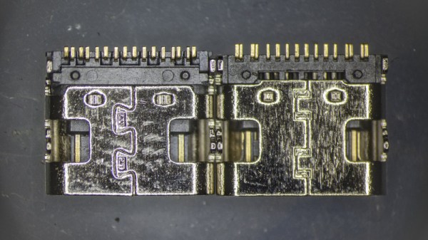
If you’ve ever dreamed of building a proper spectrometer, it looks like the ESPROS epc901 CCD sensor is absolutely worth your attention. It’s fast, sensitive, easy to interface with, and at just $24 USD, it won’t break the bank. There’s only one problem: implementing it in your project means either working with the bare 2×16 0.5 mm pitch BGA device, or shelling out nearly $1,400 USD for the development kit.
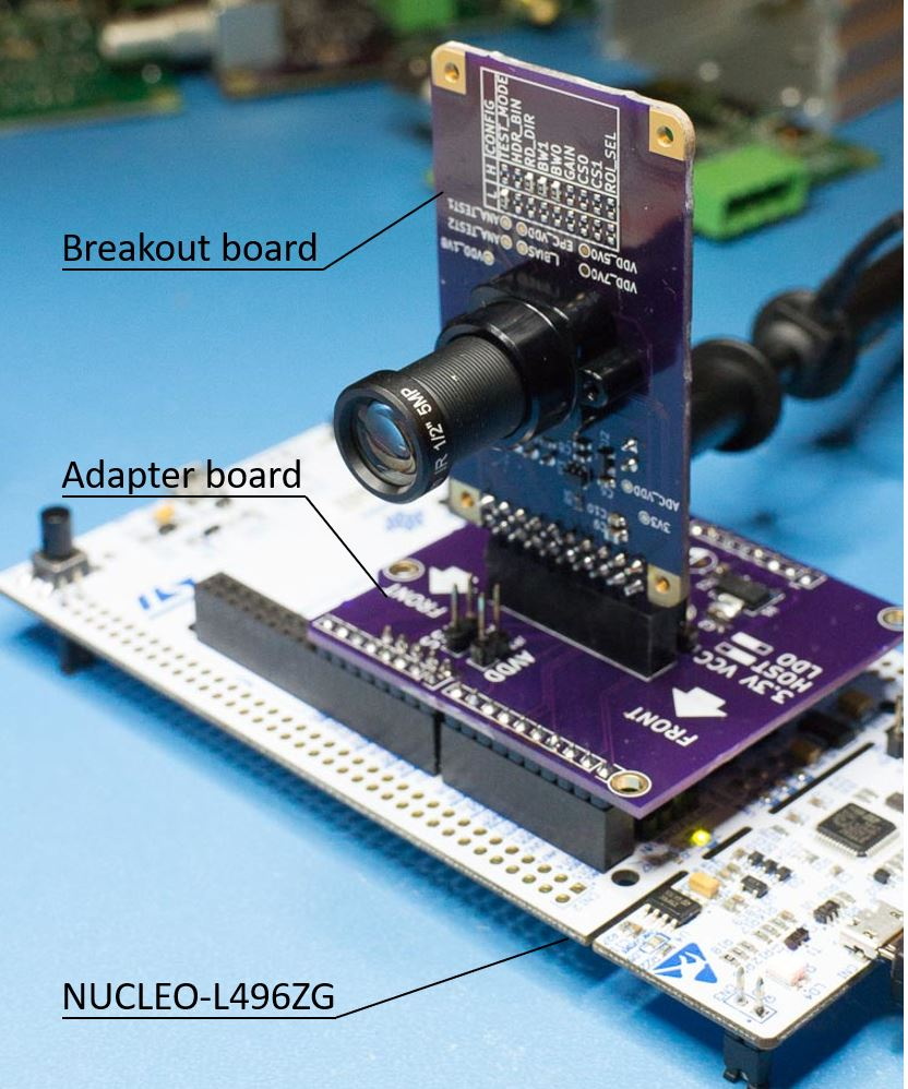 Thankfully, [Adrian Studer] has come up with a compromise. While you’ll still need to reflow the BGA to get it mounted, his open hardware breakout and adapter boards for the ESPROS epc901 make the sensor far easier to work with.
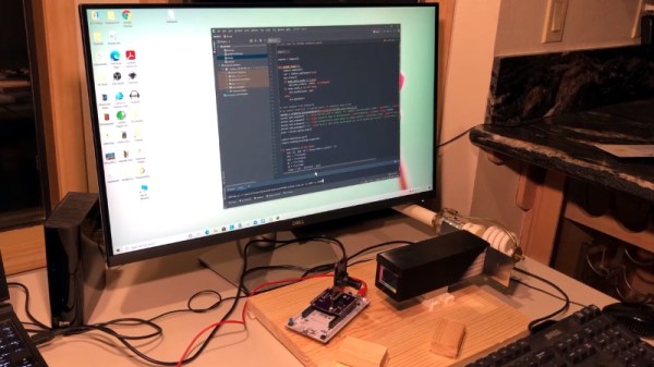
It’s not just a hardware solution either, he also provides firmware code for the STM32L4 based Nucleo development board and some Python scripts that make it easy to pull data from the sensor. The firmware even includes a simple command line interface to control the hardware that you can access over serial.
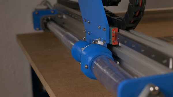
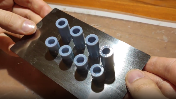
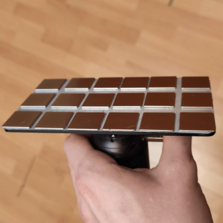
With the sensor successfully wrangled, [Adrian] partnered with [Frank Milburn] to build an affordable spectrometer around it. The design makes use of a 3D printed chamber, a simple commercial diffraction grating, and an array of entrance slits ranging from 0.5 to 0.0254 millimeters in width that were laser-cut into a sheet of stainless steel.
In the videos after the break, you can see the finished spectrometer being used to determine the wavelength of LEDs, as well as a demonstration of how the high-speed camera module is able to study the spectral variations of a CFL bulb over time. [Adrian] tells us that he and [Frank] are open to suggestions as to what they should point their new spectrometer at next, so let them know in the comments if you’ve got any interesting ideas.
We’ve seen an incredible number of spectrometer builds over the years, and some of the more recent ones are really pushing the envelope in terms of what the DIY scientist is capable of doing in the home lab. While they’re still fairly niche, these instruments are slowly but surely finding their way into the hands of more curious hackers.
Continue reading “High-Speed Spectrometer Built With Cheap Linear CCD”