Amateur radio has a couple of sweet allocations in the VHF bands, but because the signals don’t reflect off the ionosphere like shortwave signals, the use is limited basically to line-of-sight. One workaround is to use a repeater with a tall antenna, but that requires a lot of infrastructure or a mountainside lair.
What if you could just fly your antenna up in a drone? Well, for starters, you’d run out of batteries pretty quickly unless you could power it remotely. And if you try to tether it, the supply wires end up being too heavy to lift. Or do they?!?!
If you were to ask someone who works with RF a lot and isn’t lucky enough to do it for a commercial entity with deep pockets what their test instrument of desire would be, the chances are their response would mention a vector network analyser. A VNA is an instrument that measures the S-parameters of an RF circuit, that rather useful set of things to know whose maths in those lectures as an electronic engineering student are something of a painful memory for some of us.
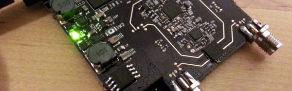
The reason your RF engineer respondent won’t have a VNA on their bench already will be fairly straightforward. VNAs are eye-wateringly expensive. Second-hand ones are in the multi-thousands, new ones can require the keys to Fort Knox. All this is no obstacle to [Henrik Forstén] though, he’s built himself a 30MHz to 6 GHz VNA on the cheap, with the astoundingly low budget of 200 Euros.
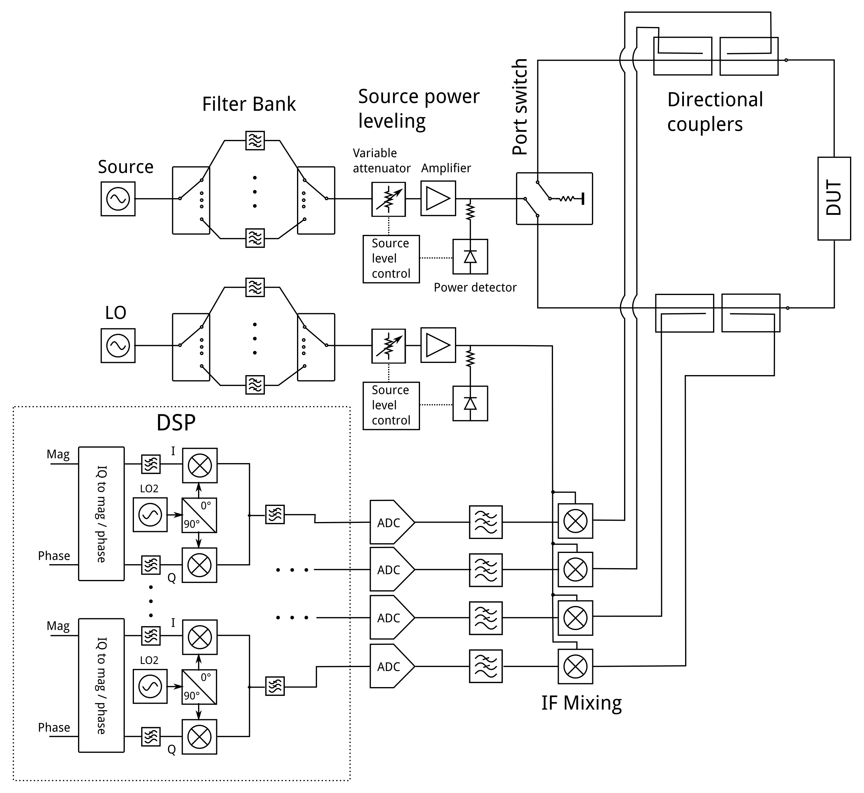
The operation of a VNA
On paper, the operation of a VNA is surprisingly simple. RF at a known power level is passed through the device under test into a load, and the forward and reverse RF is sampled on both its input and output with a set of directional couplers. Each of the four couplers feeds what amounts to an SDR, and the resulting samples are processed by a computer. His write-up contains a full run-down of each section of the circuit, and is an interesting primer on the operation of a VNA,
[Henrik] admits that his VNA isn’t as accurate an instrument as its commercial cousins, but for his tiny budget the quality of his work is evident in that it is a functional VNA. He could have a batch of these assembled and he’d find a willing queue of buyers even after taking into account the work he’s put in with his pricing.
If you are someone whose interests lie in the field of RF, you won’t need telling about the endless field of new possibilities opened up by the advent of affordable software defined radio technology. If you are a designer or constructor it might be tempting to believe that these radios could reduce some of the problems facing an RF design engineer. After all, that tricky signal processing work has been moved into code, so the RF engineer’s only remaining job should be to fill the not-so-huge gap between antenna and ADC or DAC.
In some cases this is true. If you are designing an SDR front end for a relatively narrow band of frequencies, perhaps a single frequency allocation such as an amateur band, the challenges are largely the same as those you’d find in the front end of a traditional radio. The simplest SDRs are thus well within the abilities of a home constructor, for example converting a below-100kHz-wide segment of radio spectrum to the below-100kHz baseband audio bandwidth of a decent quality computer sound card which serves as both ADC and DAC. You will only need to design one set of not-very-wide filters, and the integrated circuits you’ll use will not be particularly exotic.
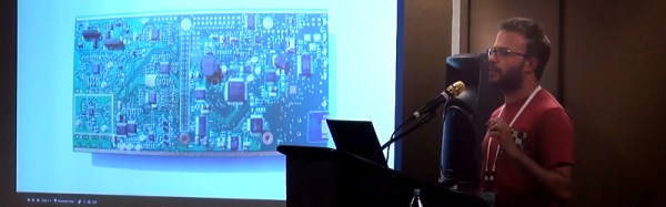
But what happens if the SDR you are designing is not a simple narrow-band device? [Chris Testa, KD2BMH] delivered a talk at this year’s Dayton Hamvention looking at some of the mistakes he made and pitfalls he encountered over the last few years of work on his 50MHz to 1GHz-bandwidth Whitebox handheld SDR project. It’s not a FoTW in the traditional sense in that it is not a single ignominious fail, instead it is a candid and fascinating examination of so many of the wrong turnings a would-be RF engineer can make.
The video of his talk can be found below the break, courtesy of Ham Radio Now. [Chris]’s talk is part of a longer presentation after [Bruce Perens, K6BP] who some of you may recognise from his activities when he’s not talking about digital voice and SDRs. We’re jumping in at about the 34 minute mark to catch [Chris], but [Bruce]’s talk is almost worth an article in itself..
Radio telescopes are one of the more high-profile pieces of scientific apparatus. There is an excitement to stories of radio astronomers of old probing the mysteries of the Universe on winter nights in frigid cabins atop massive parabolas, even if nowadays their somewhat more fortunate successors do the same work from the comfort of their labs using telescopes that may be on the other side of the world.
You might think if you look at the Arecibo Observatory, Lovell Telescope, or other famous pieces of apparatus, that this is Big Science, out of reach for mere mortals such as yourself without billion-dollar research programs. Maybe [Paul Scott] and [Allen Versfeld]’s Tiny Radio Telescope project will change that view.
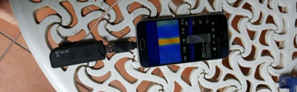
The NRAO published a radio telescope design a few years ago for use mainly as an educational tool, the Itty Bitty Telescope. It used a satellite TV dish and LNB feeding a signal meter as a simple telescope to detect the Sun, and black body radiation from the surrounding objects. It’s a simple design for kids to get their heads around, and [Scott] and [Allen] have set out to turn it into something more useful with an RTL-SDR instead of a signal meter and a motorised mount for automated observations.
This is one of those projects on Hackaday.io that moves slowly but you know will eventually deliver on its promise. With a 1m dish and a consumer LNB it’s never going to make a discovery that will rock the world, but that’s not the point. It may be science that the astrophysicists moved on from decades ago, but it’s still quite an achievement that the radio sky can be imaged using such mundane equipment.
There’s a problem with software defined radio. It’s not that everyone needs to re-learn what TEMPEST shielding is, and it’s not that Bluetooth is horribly broken. SDR’s biggest problem is one of bandwidth and processing. With a simple USB TV Tuner, you can listen in on aircraft, grab Landsat images from hundreds of miles up, or sniff the low-power radios used in Internet of Things things. What you can’t do is make your own WiFi adapter, and you can’t create your own LTE wireless network. This is simply a problem of getting bits from the air to a computer for processing.
At HOPE last weekend, the folks behind the very capable LimeSDR and a new company working with Lime’s hardware laid out the possibilities of what software defined radio can do if you make a link to a computer very fast, and add some processing on the SDR itself.
[Lukas] started his epic SDR-from-scratch build when he was 16. Projects like this aren’t completed overnight. (He’s now 18. We’re impressed.)
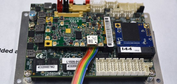
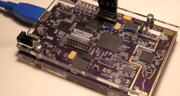
The project itself is a Software-Defined Radio built on top of the 12-bit Analog Devices AD9364 transceiver IC. A big fat FPGA takes the data and runs it off to a USB 3.0 interface, which is necessary for the amount of data this thing will be producing — he’s got it receiving 56 MHz of bandwidth. In short, this is an SDR peripheral that’s in the big leagues.
After two years of work and (only!) three revision, [Lukas] got the thing working. Read his writeup for the blow-by-blow account. In the end, a 6-layer board was necessary for the routing to get the full speed out of the clocking, and he discovered the reason that you use exactly the specified bias resistors — the expensive ADC chip gets very hot. But he didn’t give up, and in the end he pulled off a project of immense complexity. In his own words:
I have discovered that taking on large projects, even when not knowing how to tackle problems that might arise, is a very effective way of learning for me. It’s just important to be persistent, as I’ve seen that almost any problem can be solved on your own — which is incredibly rewarding — even if you get stuck and seem to not make progress for a while.
[Lukas] is now working on the software. He’s already got a hacked osmocom driver working, so it plays nice with GNURadio.
Of course, there are tons of ways to get into SDR without building your own from scratch, but we applaud [Lukas] for going the hard way. If you’re tempted to follow in his footsteps, have a look at [Michael Ossmann]’s great talk on making the RF design process as tractable as possible.
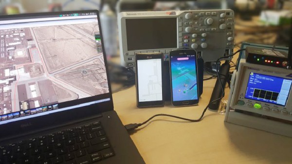
To [Stefan Kiese], this isn’t much more than an exercise. He’s not even playing Pokemon Go. To squeeze a usable GPS signal out of his HackRF One, a $300 Software Defined Radio, [Stefan] uses an external precision clock. This makes up for the insufficient calibration of the HackRF’s internal clock, although he points out that this might also be fixed entirely in software.