Mephisto III Internet Radio

Avid Hackaday reader [Matthias] told us he takes a lot of inspiration from our site. That’s quite a compliment, because his work is both inspiring and beautiful. [Matthias] wanted to build a UI using JavaFX, so he made a really nice-looking Raspberry Pi-based Internet radio. We featured his previous radio build a few months ago when he modified an old Bakelite unit.

The Mephisto III is enclosed in a handsome oak cabinet built by [Matthias]’ father. Like his previous build, this one uses the Google Music interface to play MP3s and streams radio from the web. He also added weather and a clock, which is a nice touch. In addition to the Raspi and a USB WLAN stick, [Matthias] is using two relays. One relay powers the amplifier and the other enables the display. [Matthias] is impressed with the JavaFX API, but found that the performance of the Raspberry Pi is insufficient for smooth multithreading. He considered switching to a BeagleBone Black, but it has no component out.

If you want to be able to listen to vinyl, too, check out this killer media center. If you have lost your taste for Pi, build yourself a web radio from a tiny router.

[Thanks Matthias]

Making A Variable RF Signal Sampler

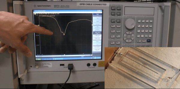
One of [Brian]’s hobbies is Amateur Ham radio, in which it is usually required to check that the transmitted signals are within specifications. As it isn’t safe to connect the radio’s output directly to measuring equipment due to the high voltages involved, [Brian] made his own dedicated RF signal sampler. It works by using capacitive coupling between the signal you wish to sample and a high impedance output. The latter can then safely be connected to an oscilloscope or spectrum analyzer for monitoring.

In the picture you see above, the air gap between the core signal conductor and the output plays the role of a capacitor. By adjusting its length you can therefore vary the output signal’s voltage range. The sampler is built using a die-cast aluminium enclosure which is 52x38x27mm. As you may have guessed, due to the case geometry the output attenuation will depend on the signal’s frequency. [Brian] tested the unit using a 30MHz signal generator and printed this frequency attenuation graph while also varying the air gap.

Build A Cheap Airplane ADS-B Radio Receiving Tracking Station

Do you have commercial or general aviation flying over your home or near your home? Would you like to know more about these airplanes: identity, heading, speed, altitude and maybe GPS data along with even more information? Well then [Rich Osgood] has just the project for you and it’s not that expensive to set up. [Rick] demonstrates using a cheap USB dongle European TV tuner style SDR (software defined radio) tuner that you can get for under $30 to listen in on the Automatic Dependent Surveillance-Broadcas (ADS-B) (dead link, try the Internet Archive version) 1090 MHz mode “S” or 978 MHz mode “UAT” signals being regularly transmitted from these aircraft.

He steps us through configuring the radio to use a better antenna for improved reception then walks through detailed software installation and set up to control the radio receiver as well as pushing the final decoded data to mapping software. This looks like a fascinating and fun project if you live near commercial airways. You won’t need a license for this hack because you’re only listening and not transmitting, plus these are open channels which are legal to receive.

There are some frequencies you are not legally allowed to eavesdrop on—private communications for residential wireless telephones and cellular frequencies to name just a few (Code of Federal Regulations Title 47, Part 15.9). So remember you do have to be careful and stay within legal frequencies even if your equipment is not restricted from such reception. Also note that just because you have a legal right to intercept conversations or data on some frequencies it could be illegal to publicly share the intercepted content or any details on the reception or decoding (just saying for the record).

We wonder if [Rick] could partner with [G. Eric Rogers] to upgrade [Eric’s] motorized telescope airplane tracking system to extrapolate the radio telemeter data into vector data so his Arduino can track without relying on a video feed. That merger might just get them both on a short TSA list.

Join us after the break for some extra informational links and to watch the video on setup, installation and usage of this cheap airplane tracking rig.

Continue reading “Build A Cheap Airplane ADS-B Radio Receiving Tracking Station”

Tape Measure VHF Yagi Antenna

tap measure yagi vhf antenna

Radio direction finding and fox hunting can be great fun and is a popular activity with amateur radio (ham radio) enthusiasts. These antennas are great and are not only good for finding transmitters but also will greatly increase directional distance performance including communicating with satellites and the international space station (ISS).

[jcoman] had a nephew who was interested in learning about amateur radio so [jcoman] figured building and using a cheap and portable 2 meter band VHF Yagi style beam antenna would be the perfect activity to captivate the young lad’s interest in the hobby.

His design is based on [Joe Leggio’s] (WB2HOL) design with some of his own calculated alterations. We have seen DIY Yagi antenna designs before but what makes this construction so interesting is that the elements come together using bits of cut metal tape measure sections. These tape measure sections allow the Yagi antenna, which is normally a large and cumbersome device, to be easily stowed in a vehicle or backpack. When the antenna is needed, the tape measure sections naturally unfold and function extremely well with a 7 dB directional gain and can be adjusted to get a 1:1 SWR at any desired 2 m frequency.

The other unique feature is that the antenna can be constructed for under $20 if you actually purchase the materials. The cost would be even less if you salvage an old tape measure. You might even have the PVC pipes, hose clamps and wire lying around making the construction nearly free.

We were quite surprised to find that such a popular antenna construction method using tape measure elements had not yet been featured on Hackaday. For completeness this is not the only DIY tape measure Yagi on Instructables so also check out [FN64’s] 2 m band “Radio Direction Finding Antenna for VHF” and [manuka’s] 70 cm band “433 MHz tape measure UHF antenna” postings. The other Yagi antenna designs featured on Hackaday were “Building a Yagi Uda Antenna” and “Turning an Easter Egg Hunt into a Fox Hunt” but these designs were not so simple to construct nor as cleverly portable.

Retrotechtacular: Tube Amplifiers

retrotechtacular-how-tube-amps-work

It’s hard to beat this vintage reel for learning about how vacuum tube amplifiers work. It was put together by the US Army in 1963 (if we’re reading the MCMLXIII in the title slide correctly). If you have a basic understanding of electronics you’ll appreciate at least the first half of the video, but even the most learned of radio enthusiasts will find something of interest as they make their way through the 30-minute presentation.

The instruction begins with a description of how a carbon microphone works, how that is fed to a transformer, and then into the amplifier. The first stage of the tube amp is a voltage amplifier and you’ll get a very thorough demo of the input voltage swing and how that affects the output. We really like it that the reel discusses getting data from the tube manual, but also shows how to measure cut-off and saturation voltage for yourself. From there it’s off to the races with the different tube applications used to make class A, B, and C amplifiers. This quickly moves onto a discussion of the pros and cons of each amplifier type. See for yourself after the jump.

Continue reading “Retrotechtacular: Tube Amplifiers”

Current Limiting Diode Use And Tutorial

Current limiting diode 1

Not that this happens often, but what do you do when faced with a repair where you don’t know the power source but you do know you have to drive LED backlighting? When faced with this dilemma [Eric Wasatonic’s] solution was to design for ambiguity. In this interesting hack repair [Eric] needed to restore backlighting for an old car stereo LCD display. First he guaranteed he was working with a DC power source by inserting a small full-wave bridge rectifier. Then knowing he needed 4 mA to power each LED for backlighting he used some 1978 vintage current limiting diodes designed to pass 2mA each regardless of voltage source, within limits of course.

Sure this is a simple hack repair but worthy of being included in anyone’s bag of tricks. Like most hacks there is always knowledge to be gained. [Eric] shares a second video where he uses a curve tracer and some datasheets to understand how these old parts actually tick. These old 1N5305 current limiting diode regulators are simply constructed from a JFET with an internal feedback resistor to its gate which maintains a fixed current output. To demonstrate the simplicity of such a component, [Eric] constructs a current limiting circuit using a JFET and feedback potentiometer then confirms the functionality on a curve tracer. His fabricated simulation circuit worked perfectly.

There was a little money to be made with this repair which is always an added bonus, and the recipient never reported back with any problems so the fix is assumed successful. You can watch the two videos linked after the break, plus it would be interesting to hear your thoughts on what could have been done differently given the same circumstances.

Continue reading “Current Limiting Diode Use And Tutorial”

Automatic Antenna Tuner

Automatic Antenna Tuner

To get the best power transfer into an antenna, tuning is required. This process uses a load to match the transmission line to the antenna, which controls the standing wave ratio (SWR).

[k3ng] built his own automatic antenna tuner. First, it measures the SWR of the line by using a tandem match coupler. This device allows the forward and reflected signals on the line to be extracted. They are buffered and fed into an Arduino for sampling. Using this data, the device can calculate the SWR. The RF signal is also divided and sampled to measure frequency.

To automate tuning, an Arduino switches a bank of capacitors and inductors in and out of the circuit. By varying the load, it can find the ideal matching for the given antenna and frequency. Once it does, the settings are stored in EEPROM so that they can be recalled later.

After the break, check out a video of the tuner clicking its relays and matching a load.

Continue reading “Automatic Antenna Tuner”