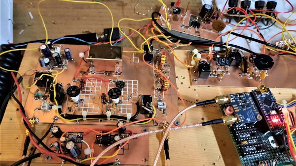
Arduino Becomes Superhet With A Little Help From Friends

A radio receiver is always a fun project. [Jayakody2000lk] decided that his new superheterodyne design would use an Arduino and it looks like it came out very nicely. The system has four boards. An off-the-shelf Arduino, a Si5351 clock generator board (also off-the-shelf), and two custom boards that contain the IF amplifier and mixer.

The receiver started out in 2015 without the Arduino, and there’s a link in the post to that original design. Using the Si5351 and the Arduino replaces the original local oscillator and there have been other improvements, as well. You can see a video about the receiver below.

Tuning is by a rotary encoder and the current software lets you tune from about 4.75 MHz to a little over 15.8 MHz. Of course, you could change to any frequency the Si5351 can handle as long as the mixer and other components can handle it. The IF frequency is the usual 455 kHz.

If you decide to build this yourself, the design files are on GitHub. Overall a very nice and neat design. We are always amazed how little radio architecture has changed since Edwin Armstrong’s day. Of course, we have better components, even if they aren’t meant for radio purposes.

Continue reading “Arduino Becomes Superhet With A Little Help From Friends”

Shortwave Radio Picks Up Sideband

With the push to having most of a radio receiver as part of a PC, it might seem odd to have a standalone communication receiver, but [OM0ET] reviews the latest one he picked up, an ATS25. Inside isn’t much: a battery, a speaker, an encoder, and a Si4732 that provides the RF muscle.

It appears the receiver is pretty broadband which could be a problem. [OM0ET] suggests adding selectivity in the antenna or adding an extra board to use as a bandpass filter.

Continue reading “Shortwave Radio Picks Up Sideband”

A Bird 43 wattmeter and its homebrew equivalent

Homebrew Wattmeter Pays Homage To Sturdy Original

If there’s one instrument that hams and other radio enthusiasts covet, it’s the venerable Bird 43 Thruline wattmeter. The useful RF tool has barely changed in the nearly 70 years since it was first introduced, and they’re built like a tank. This makes Bird meters highly desirable, and therefore quite expensive either brand new or on the swap-meet circuit.

But radio amateurs are nothing if not resourceful, and building a homebrew version of the Bird wattmeter (in Portuguese; Google translate tool at the bottom of the page) as Brazilian ham [Luciano Sturaro (PY2BBS)] did is a good way to get your hands on one. Granted, [Luciano] had a head start: a spare line set, which is the important bit from a Bird wattmeter. The machined metal part is in effect an air-insulated section of coaxial cable that the RF signal passes through on its way from transmitter to antenna. A “slug” is inserted into the cavity in the line set to sense the RF and couple it to the meter electronics; the slug can be rotated to measure RF traveling in either direction, allowing the user to determine how much RF is getting reflected by the antenna system.

[Luciano]’s version of the meter is faithful to the sturdy construction of the original, with a solid steel case that mimics its classic lines — the case even sports the same color scheme and stout leather carry handle. There are some changes to the electronics, and the meter movement itself is different from the original, but all in all, the “Buzz 50” looks fantastic. We especially love the detailed nameplate as an homage to Bird.

The thing about Bird — and Bird-like — meters is that the slugs are like potato chips; you can’t have just one. Curious as to how these slugs work? Check out this slug repair project.

[Featured image of Bird 43 Wattmeter: Martin RF Supply]

Thanks to [Niko Huenk] for the tip!

The Simplest FT8 Transceiver You’ll Ever Build

Probably the most interesting facets of amateur radio in 2021 lie in the realm of digital modes. Using the limitless possibilities of software defined radios has freed digital radio communication from the limits of what could be done with analogue electronics alone, and as a result this is a rare field in which radio amateurs can still be ahead of the technological curve. On of these newer digital modes is FT8 created by the prolific [Joe Taylor K1JT].

And it’s for this  mode that [Charles Hill] has created an easy-to-build transceiver. Its brains are aTeensy 3.6, while the receive side is a Si4735 receiver chip and the transmitter is a Si5351 programmable clock chip driving a Mini-Circuits GVA84 power amplifier with an appropriate filter. The interface is via a touchscreen display. It relies on existing work that applies a patch on-the-fly to the Si4735 receiver chip for SSB reception, and another project for the FT8 software.

The charm of this transceiver is that it can be assembled almost in its entirety from modules. Some radio amateurs might complain that homebrew radios should only use the most basic of components assembled from first principles, but the obvious answer to that should be that anything which makes radio construction easier is to be welcomed. If the 100 mW output power seems a bit low it’s worth remembering that FT8 is a weak signal mode, and given the right propagation conditions the world should be able to hear it despite the meagre output.

We’ve featured quite a few radios using the Si47XX series, which can be made into very tidy receivers indeed.

A 3-6-9 Antenna Pulls In The Signals

Every time we see a dispatch from [Mr. Carlson], we imagine it is being beamed from his orbital station packed full of vintage radio gear. We are certain the reality is more terrestrial, but if we were going to build an orbiting lab, it might look like [Carlson’s] shack. In his latest communique, he shares his progress working on a high-performance 3-6-9 receiving antenna design and you can see it in the video below.

Although the antenna isn’t done, it is already working and looks impressive. There’s a lot of wire, so this probably isn’t a condo-friendly solution. The name of the antenna derives from the three wires, one tuned for 3 MHz, one for 6 MHz, and the other for 9 MHz.

Continue reading “A 3-6-9 Antenna Pulls In The Signals”

GNU Radio Decodes Voyager Data

With the 44th anniversary of the launch of Voyager I, [Daniel] decided to use GNU Radio to decode Voyager data. The data isn’t live, but a recording from the Green Bank Telescope. The 16 GB file is in GUPPI format which stores raw IQ samples.

The file contains 64 frequency channels of just under 3MHz each. The signal of interest is in one channel, so it is easy to just throw away the rest of the data.

Continue reading “GNU Radio Decodes Voyager Data”

A Raspberry Pi next to a small circuit board

An Inexpensive FM Receiver For The Raspberry Pi

At this point, there are no shortage of impressive hacks for the Raspberry Pi. [Dilshan Jayakody] recently documented his experience in designing and building an inexpensive FM Stereo Receiver for the Pi platform, and the results are impressive.

Quite a few FM receiver projects center around the RDA5807 or TEA5767 ICs, however [Dilshan] has used the QN8035 by Quintic Corporation in his build. A handful of discrete components on a pleasing single-sided PCB is all that is needed to interface the QN8035 with the Pi’s I2C bus.

After demonstrating that the FM tuner could be, well, tuned at the command line, [Dilshan] then coded a smart looking GUI application that makes tuning a breeze. The software allows the listener to manually and automatically scan through FM stations, decode program service data, control the volume, and display the RSSI and SNR readings from the tuner.

As we reported earlier, FM radio is on a slow decline into obsolescence. This latest project isn’t aiming to break new ground, however its simplicity and inexpensive components are the perfect combination for beginner hackers and radio enthusiasts alike. More details can be found over on Hackaday.io. The schematic, source code and bill of materials can be found on GitHub.

Continue reading “An Inexpensive FM Receiver For The Raspberry Pi”