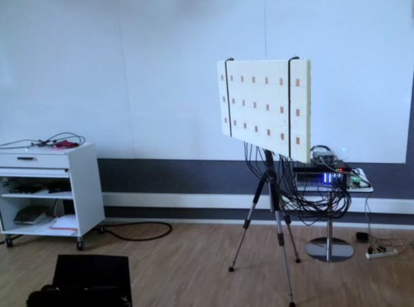
The days when software defined radio techniques were exotic are long gone, and we don’t miss them one bit. A case in point: [Laakso Mikko’s] research group has built a multichannel receiver using 21 cheap RTL-SDR dongles to create a phase coherent array. This is useful for everything from direction finding and passive radar or beam forming. The code is also available on GitHub.
The phase coherence does require the dongle’s tuner can turn off dithering. That means the code only works with dongles that use the R820T/2. The project modifies the dongles to use a common clock and a switchable reference noise generator.
[Doug]’s newly-installed Yaesu FT-891 mobile transceiver failed to power up despite a careful installation, and it turns out to have ultimately been caused by a reversed cable. There’s a happy ending, however. Since the only real casualties were a blown resettable fuse and a badly-burned resistor that damaged the PCB, [Doug] was able to effect a repair. Things could have been worse, but they also could have been better. Damage could have been prevented entirely with some better design, which [Doug] explains during his analysis of what went wrong.
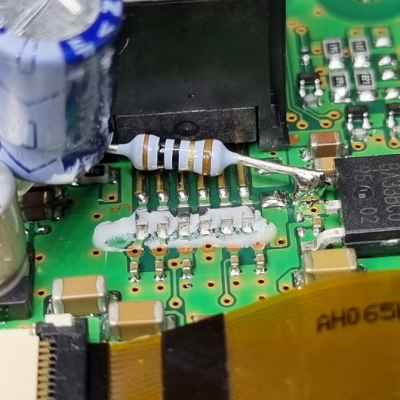
The destroyed SMT resistor and pads were easily replaced with a through-hole version, thanks to the schematics.
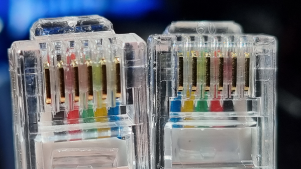
The main problem was that the generic RJ12 cable that [Doug] used to connect radio components had its connections reversed. This would not be a problem if it was used to connect a landline telephone to the wall, but it was a big problem when used to connect the radio components together. According to the radio schematics, the two center wires carry +13 V and GND, which meant that a reversed cable delivered power with reversed polarity; never an optimal outcome.
Once the reversed power arrived at the other end, [Doug] discovered something else. Diodes whose job would be to protect against reverse polarity were marked DO NOT INSTALL, probably to shave a few cents off the bill of materials. As a result, the full 13 V was soaked up by a 1/8 W surface mount resistor which smoldered and burned until a fuse eventually blew, but not before the resistor and pads were destroyed. Thankfully, things cleaned up well and after replacing the necessary parts and swapping for a correct cable, things powered up normally and the mobile radio was good to go.
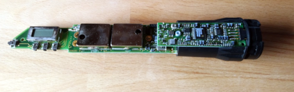
Software defined radio and widespread software-controlled PLL synthesis for RF has been a game changer. Things like the RTL-SDR can be any kind of radio you like on almost any frequency you like. But not every SDR or PLL system opens the configuration doors to you, the end user. That was the problem [vgnotepad] faced when trying to connect a Sennheiser wireless microphone to some receivers. They didn’t use the same frequencies, even though the transmitter was programmable. The solution to that is obvious — hack the transmitter!
The post is only part one of several parts and if you read to the end, you’ll learn a lot about what’s inside the device and how to crack it. Luckily, the device uses a PIC processor, so getting to the software wasn’t a big issue.
Those readers whose interests don’t lie in the world of amateur radio might have missed one of its firsts, for the last year or two amateurs have had their own geostationary satellite transponder. Called Es’hail-2 / AMSAT Phase 4-A / Qatar-OSCAR 100, it lies in the geostationary orbit at 25.9° East and has a transponder with a 2.4 GHz uplink and a 10.489 GHz downlink. Receiving the downlink is possible with an LNB designed for satellite TV, but for many hams the uplink presents a problem. Along comes [PY1SAN] from Brazil with a practical and surprisingly simple solution using a mixture of odd the shelf modules and a few hand-soldered parts.
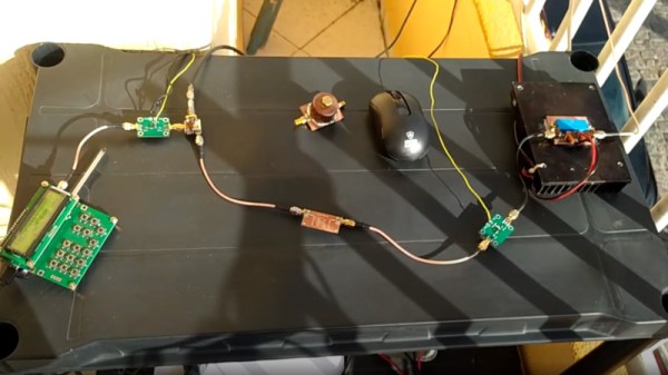
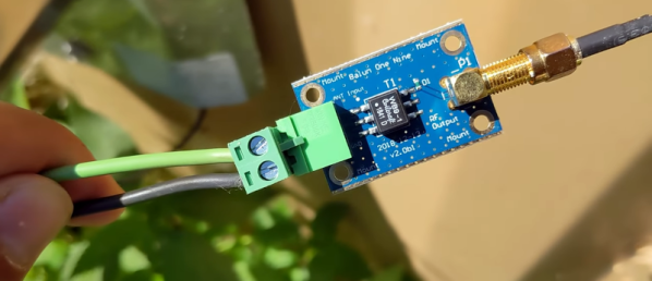
An upconverter follows a simple enough principle, the radio signal is created at a lower frequency (in this case by a 435 MHz transmitter) and mixed with a signal from a local oscillator. A filter then picks out the mixer product — the sum of the two — and amplifies it for transmission. [PY1SAN]’s upconverter takes the output from the transmitter and feeds it through an attenuator to a MiniCircuits mixer module which takes its local oscillator via an amplifier from a signal generator module. The mixer output goes through a PCB stripline filter through another amplifier module to a power amplifier brick, and thence via a co-ax feeder to a dish-mounted helical antenna.
The whole thing is a series of modules joined by short SMA cables, and could probably be largely sourced from a single AliExpress order without too much in the way of expenditure. It’s by no means easy to get on air via Es’hail-2, but at least now it need not be impossibly expensive. Even the antenna can be made without breaking the bank.
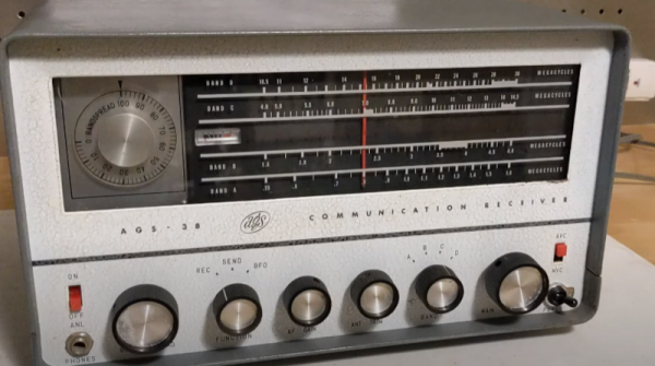
We’ll admit we haven’t heard of the AGS-38, it reminds us of the shortwave receivers of our youth, and it looks like many that were made “white label” by more established (and often Japanese) companies. [Jeff] found a nice example of this Canadian radio and takes it apart for our viewing pleasure. He also found it was very similar to a Layfayette receiver, also made in Japan, confirming our suspicions.
The radio looks very similar to an Eico of the same era — around the 1960s. With seven tubes, radios like this would soon be replaced by transistorized versions.
[VK3YE] knows there are at least two things wrong with the cheap antennas you get with most SDR dongles. First, they are too short. You’d like to have enough to pull out a quarter wavelength on the longest frequency you want to operate. The second problem is there’s no real ground. He fixed both of these problems, as you can see in the video below.
The result might be called an ugly duckling rather than a rubber ducky. But it does seem to work. You could probably come up with something nicer to reseal the base, but the tape does work. A nice 3D printed housing would work, too, and might improve the appearance. We also thought about the goop you use on tool handles.
We actually have simply cut these antennas off and reused the cable and connector to hook up a better antenna. You might get more mileage out of that approach. On the other hand, the magnetic base and reasonably small form factor is pretty attractive.
Dipoles are a classic builder’s antenna, after all they are usually little more than two pieces of wire and a feedline. But as [Rob] shows us in the video below, there are a few things to consider.
The first thing is where to get the wire. A damaged extension cord donated the wire. That’s actually an interesting idea because you get multiple wires the same length inside the extension cord. Continue reading “A Cheap Dipole Antenna From An Extension Cord”→