Amateur radio operators and shortwave listeners have a common enemy: QRM, which is ham-speak for radio frequency interference caused by man-made sources. Indiscriminate, often broadband in nature, and annoying as hell, QRM spews forth from all kinds of sources, and can be difficult to locate and fix.
But [Emilio Ruiz], an operator from Mexico, got a little help from Mother Nature recently in his quest to lower his noise floor. Having suffered from a really annoying blast of RFI across wide swaths of the radio spectrum for months, a summer thunderstorm delivered a blessing in disguise: a power outage. Hooking his rig up to a battery — all good operators are ready to switch to battery power at a moment’s notice — he was greeted by blessed relief from all that noise. Whatever had caused the problem was obviously now offline.
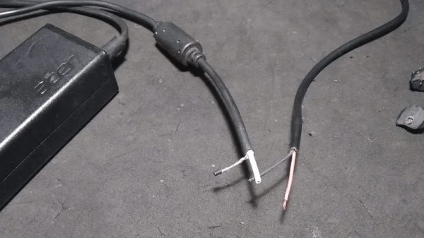
Rather than waste the quiet time on searching down the culprit, [Emilio] worked the bands until the power returned, and with it the noise. He killed the main breaker in the house and found that the noise abated, leading him on a search of the premises with a portable shortwave receiver. The culprit? Unsurprisingly, it was a cheap laptop power supply. [Emilio] found that the switch-mode brick was spewing RFI over a 200-meter radius; a dissection revealed that the “ferrite beads” intended to suppress RFI emissions were in fact just molded plastic fakes, and that the cord they supposedly protected was completely unshielded.
We applaud [Emilio]’s sleuthing for the inspiration it gives to hunt down our own noise-floor raising sources. It kind of reminds us of a similar effort by [Josh (KI6NAZ)] a while back.