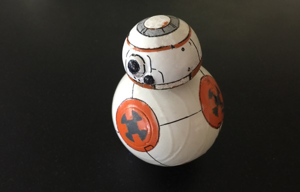
With a background in software engineering, [Kris Temmerman] decided to make a physical demonstration of his knowledge in the form of a six axis robotic arm… the final product is a delicious display of mechanical eye candy.
Built from mostly aluminum stock, [Kris] machined the bulk of his parts with a CNC mill which he picked up for cheap from China. These custom pieces coupled with some hefty stepper motors ensure the arm’s accuracy as it twists freely and slides along the gantry it’s mounted to. Though the majority of the arm is metal, the hand at the end of his robot was built with 3D printed parts and can be switched out with the future attachments [Kris] plans to design. This classic gripper piece is driven separately with its own Arduino brain controlling the individual servos in the fingers. 
Each finger includes some load bearing sensors which [Kris] harvested from an old scale so that the gripper can tell whether or not it has a hold of an object without crushing it. To orchestrate the robot’s movement, he wrote some nice looking software in C++ which visualizes the inverse kinematics at work in each point of articulation. For the sake of demonstrating his creation in action, he whipped up a basic demo that can locate and move colored blocks laid at random on a surface. A small camera mounted on the hand determines the orientation of the blocks relative to the machine so that the wrist can rotate itself in the proper alignment in order to pick them up.
[Kris] documented the build of his robot in a fascinating speed video which includes footage of the finished arm in action at the end:
Continue reading “This Home-Made 6-Axis Robotic Arm Is Quite The Looker”


[Max] designed all of the mechanical parts himself. After weighing the advantages and disadvantages of different materials, he decided that the frame would be made from 5mm acrylic sheet. The main body of the robot has acrylic ribs that are spaced apart by threaded rods. Twelve RC servos make up all of the joints, 3 in each leg. Notice in this photo how there is one servo that immediately rotates another servo. To support the other side of the rotating servo, [Max] epoxied on a T-nut, stuck in a short length of threaded rod which is then supported in the frame by a ball bearing. Simple and effective! The upper portions of the legs are also made from acrylic sheet and the lower legs are from a cheap camera tripod. Rubber feet ensure a slip resistant stance.
Like any project, there were some hiccups along the way. First, several revisions of the gripper were necessary to get the correct tooth profile that resulted in smooth and tight movement. Also, while making the shield the spacing between banks of headers came out one header too close! On this first board [jjshortcut] just bent the pins so they would fit into the Arduino. You can’t let some minor snafu prevent forward momentum of a project!
