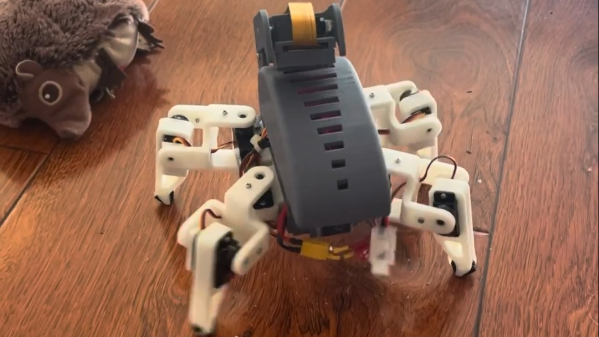
Design Files Released For The PR2 Robot

It’s always great fun to build your own robot. Sometimes, though, if you’re doing various projects or research, it’s easier to buy an existing robot and then use it to get down to business. That was very much the role of the Willow Garage PR2, but unfortunately, it’s no longer in production. However, as covered by The Robot Report, the design files have now been released for others to use.

The PR2 was built as an advanced platform with wide-ranging capabilities. It was able to manipulate objects with its 7-degrees-of-freedom end effectors, as well as visualize the real world with a variety of complex sensor packages. Researchers put it to work on a variety of tasks, from playing pool to fetching beers and even folding laundry. The latter one is still considered an unsolved problem that challenges even the best robots.

Rights to the PR2 robot landed in the hands of Clearpath Robotics, after Willow Garage was shut down in 2014. Clearpath is now providing access to the robot’s design files on its website. This includes everything from wiring diagrams and schematics, to assembly drawings, cable specs, and other background details. You’ll have to provide some personal information to get access, but the documentation you desire is all there.

We actually got our first look at the PR2 robot many years ago, way back in 2009. If you decide to build your own from scratch, be sure to hit us up on the tipsline.

Continue reading “Design Files Released For The PR2 Robot”

Rubik’s Cube Solver Does It In 4.56 Seconds

Solving Rubik’s Cubes is a learnable skill. However, to compete at the top level, you’ll have to train hard. Speed cubers can solve a 3×3 cube in under ten seconds these days, after all. [aaedmusa] was a long way off that speed, but his robot is an absolute demon that solves at a rapid pace.

The robot relies on a Teensy 4.1 microcontroller to run the show, paired with its Ethernet kit for connectivity. It runs six stepper motors via TMC2208 drivers, enabling it to directly actuate each face of the cube. Purists will note, however, that the steppers are fitted with adapters that slot directly into modified center squares on the cube. A regulation Rubik’s, this is not.

The design doesn’t feature a machine vision system to capture the state of the cube. Instead, the cube’s status must be input to a web app on an attached computer. Once the cube’s state is loaded into the program, though, the mechanical job of solving the cube can be achieved in under five seconds. Even with six actuators, that’s not fast enough to beat the human world record of 3.47 seconds, but it’s still pretty darn good.

It’s funny to think that way back in 2011, both robots and humans were so much slower at solving cubes. If only all the world’s problems were as simple as a jumbled up toy from the 1970s.

Continue reading “Rubik’s Cube Solver Does It In 4.56 Seconds”

Foldable PCB Becomes Tiny Rover

Typically, when you’re putting electronics in a robot, you install the various controller PCBs into the robot’s chassis. But what if the PCB itself was the chassis? [Carl Bugeja’s] latest design explores just that idea.

Yes, [Carl] decided to build a tiny robotic rover out of a foldable PCB. This choice was made as using a flexible foldable PCB would allow for the creation of a 3D chassis without the need for bulky connectors joining several boards together. A key part of the design was allowing the structure to unfold easily for serviceability’s sake. To that end, the structure is held together by the bolts that also act as the axles for the rover’s wheels. Even more brilliantly, the wheels are turned by motors built into the very PCB itself. Control is via a PlayStation controller, connected wirelessly to command the robot.

The little bot is surprisingly capable, especially when juiced up with a twin-cell lithium battery. It’s tiny, with minimal ground clearance, so it’s not the best at driving on rough surfaces. Having all-wheel-drive helps, though.

[Carl] specifically credits Altium Designer for making the design possible, thanks to its advanced 3D visualization tools that support foldable PCBs. Video after the break.

Continue reading “Foldable PCB Becomes Tiny Rover”

Caterpillar-Like Soft Robot With Distributed Programmable Thermal Actuation

Researchers at North Carolina State University have created a soft robot that moves in a distinctly caterpillar-like manner. As detailed in the research paper in Science Advances by [Shuang Wu] and colleagues, the robot they developed consists of a layer of liquid crystalline elastomers (LCE) and polydimethylsiloxane (PDMS) with embedded silver nanowire that acts as a heater.

The LCE is hereby designed as a thermal bimorph actuator, using a distinct thermal expansion coefficient between the LCE and PDMS sides to create a highly controllable deformation and thus motion. Since the nanowire is divided into sections that can be individually heated, the exact deformation can be quite tightly controlled, enabling the crawling motion.

(A) Schematics of the forward locomotion of a caterpillar. (B) Schematics of the reverse locomotion of a caterpillar. (C) Snapshots of the crawling robot in one cycle of actuation for reverse locomotion. (D) Snapshots of the crawling robot in one cycle of actuation for forward locomotion. (E) infrared image of the crawling robot with 0.05-A current injected in channel 1 and the tilted view of the crawling robot. (F) Infrared image of the crawling robot with 30-mA current injected in channel 2 and the corresponding tilted view of the crawling robot. (Credit: Shuang Wu, et al. (2023))

As can be seen in the video below, the motion is fairly rapid and quite efficient, as well as decidedly caterpillar-like. Although the current prototype uses external control wires that supply the current, it might be possible to integrate a power supply and control circuitry in a stand-alone robot. Since the heater works on low voltage (5 V) and relatively little power is required, this would seem to make stand-alone operation eminently possible.

Continue reading “Caterpillar-Like Soft Robot With Distributed Programmable Thermal Actuation”

Single Flex PCB Folds Into A Four-Wheel Rover, Complete With Motors

You’ve got to hand it to [Carl Bugeja] — he comes up with some of the most interesting electromechanical designs we’ve seen. His latest project is right up there, too: a single PCB that folds up into a four-wheel motorized rover.

The key to [Carl]’s design lies with his PCB brushless motors, which he has been refining since we first spotted them back in 2018. The idea is to use traces on the PCB for the stator coils to drive a 3D printed rotor containing tiny magnets. They work surprisingly well, even if they don’t generate a huge amount of torque. [Carl]’s flexible PCB design, which incorporates metal stiffeners, is a bit like an unfolded cardboard box, with two pairs of motor coils on each of the side panels. This leaves the other surfaces available for all the electronics, with includes a PIC, a driver chip, and a Hall sensor for each motor, an IMU and proximity sensor for navigation, and an ESP32 to run the show.

With machined aluminum rotors and TPU tires mounted to the folded-up chassis, it was off to the races, albeit slowly. The lack of torque from the motors and the light weight of the rover, along with some unwanted friction due to ill-fitting joints, added up to slow progress, especially on anything other than a dead flat surface. But with some tweaking, [Carl] was able to get the buggy working well enough to call this one a win. Check out the build and testing in the video below.

Knowing [Carl], this isn’t the last we’ll see of the foldable rover. After all, he stuck with his two-wheel PCB motor design and eventually got that running pretty well. We’ll be keeping an eye out for progress on this one.

Continue reading “Single Flex PCB Folds Into A Four-Wheel Rover, Complete With Motors”

Icicle Patterns With Custom Gantry

[Cranktown City] uses a number of custom-built linear rails used as gantries for various tools in the shop. The first is on a plasma cutter, which is precise but difficult to set up or repair. Another is for mounting a camera, and while it is extremely durable, it’s not the most precise tool in the shop. Hoping to bridge the gap between these two, he’s building another gantry with a custom bearing system, and to test it he’ll be using it to create patterns in icicles hanging from an eave at his shop.

While this isn’t the final destination for this gantry, it is an excellent test of it, having to perform well for a long period of time in an extremely cold environment. The bearing system consists of a piece of square steel tubing turned 45° inside another larger square steel tube and held in place with two sets of three bearings with V-shaped notches. To drive the gantry he is using a motor with a belt drive, and for this test a piece of drip irrigation is mounted to it which lets out a predetermined amount of water on top of the roof to create numerous icicles beneath with various programmed lengths.

After a few test runs the gantry system can create some icicles, although they don’t have the exact sine wave shape that [Cranktown City] programmed into it. They are varying lengths though, and with no more cold days in the forecast he’s called it a success. This isn’t the final destination for this robotic linear gantry, though, but it did help him work out some of the kinks with it beforehand. For other sources of inspiration, take a look at this linear rail system also used for driving various robotic tooling.

Continue reading “Icicle Patterns With Custom Gantry”

Meet The New Moteus BLDC Controller Board, The N1

[Josh] over at mjbots just released a new version of the moteus controller board, dubbed the moteus-n1. One change is that the volume and footprint size has been reduced. Considering many people, [Josh] included, use these controllers to operate robotic dogs, smaller is better. The previous moteus controller maxed out at 44 V, but the n1 can run at up to 54 V, allowing use of 48 V power supplies. And [Josh] improved the interface circuitry, making it much more flexible than before. This comes at an increased price, but he sells both versions — parts availability permitting. And like the previous versions of the moteus controller, this is an open source project and you’re free to build it yourself. You can check out the complete design package at the project’s GitHub repository.

One helpful point is that the firmware for the n1 is the same, it simply enables new features related to the I/O ports. This means a user could swap in a new controller with no impact to their system. Maintaining firmware compatibility was just one of the challenges [Josh] faced along the way. Squeezing additional functionality into the small number of user-exposed I/O pins was a chore, but dealing with supply chain issues was a big headache:

…make a revision that leveraged the parts I had, along with ensuring that the parts I needed were achievable to purchase in a reasonable time frame. Some parts orders for this batch were placed nearly a year ago.

Check out moteus if you need a brushless servo controller. We covered the previous major upgrade last year, which was primarily firmware and interface focused.