Most of us probably know the drudgery of getting through some coding work, with just tedious hours of monkeying around stretching ahead of us. What if this tedium were to be interrupted by an occasional reward when we did something productive, like pushing a commit or other measure of progress? That’s roughly the concept that [John Partee] started off with when his gaze fell upon one of those automated cat feeders. Cat or developer, who doesn’t like to hear the tinkle of a tasty treat falling into their bowl?
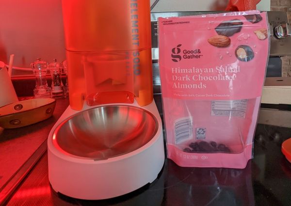
The target pet feeder is a PetKit Fresh Element Solo, which allows for objects with a size of 12×12 mm (any orientation) to be fed through the feeding mechanism. Fortunately [John]’s favorite dark chocolate-covered almonds treat fit these requirements, and he set to work to figure out the REST API call needed to trigger a manual feeding event on the cat feeder device, employing the existing PyPetKit Python library that does the heavy lifting of connecting to and communicating with PetKit’s servers, as the feeder is of course an IoT device.
This means that the event flow still depends on PetKit’s “cloud”, which may inspire some enterprising hackers to make a stand-alone version, the development of which may be assisted by [John]’s solution through a regular treat. Before taking such a solution into use, be sure to discuss it with any pets you have, as they may not quite comprehend why there’s no reward for them whenever the *tinkle* sound occurs.
Continue reading “Hacking Developers With A Cat Feeder: Who’s A Good Kitty?”