“I don’t get mad when people rip me off. I actually think its kinda cool, because imitation is the sincerest form of flattery.” — Ben Heckendorn
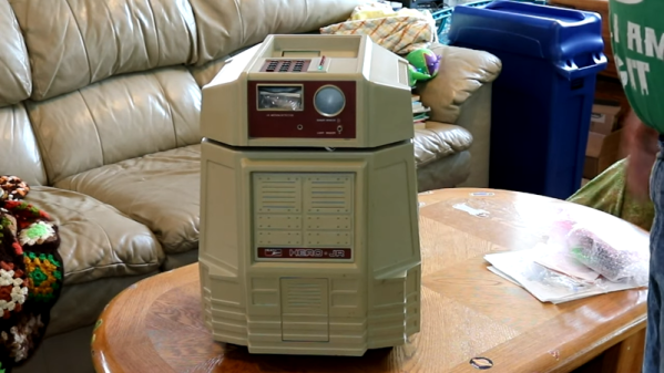
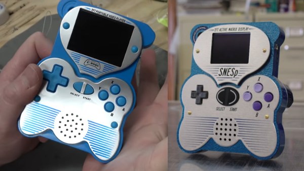
For some “hacking things together” can mean heavily borrowing from other’s work in order to make a new, derivative work. Though longtime hardware hacker, Ben Heckendorn, didn’t expect one of his early SNES handheld projects to become the inspiration for a Famicom-style clone console. There have been a number of clone consoles available online for years, and all have been made to varying levels of build quality. The subject clone console in question is called the Easegmer 12-bit Retro Console, so [Ben] decided to record his teardown of the handheld borrowing from his original design. (Video, embedded below.)
The Easegmer handheld has a “surprising” list of features according to its packaging including: sports games, logic games, memoyr games, USB charger management, double power supply option, and dirunal double backlight option. All big (and slightly misspelled) promises though the most egregious claim has to be that, “No violent games, your child’s body and mind get full exercise.”. The statement may have a modicum of truth to it, except for the fact that game 84 of 220 is literally named “Violent”. Dunking aside, the handheld does feature a standard size rechargeable battery in addition to the option of powering the device with three AAA batteries. There’s even a “fun size” screwdriver and a few replacement screws included which is more than you can say for most modern electronics.
It has been almost twenty years after [Ben] originally published his SNES portable project on his website. So as a long awaited follow-up, [Ben] plans to make a “meta-portable”. This meta portable will start with the Adobe Illustrator files he kept from that SNES portable in 2001 and incorporate pieces of the Easegmer clone console. Thus spawning a new clone of the clone of his clone…or whatever that project ends up being its sure to be worth repeating.
Continue reading “Clone Console Cribs Ben Heck’s Classic SNES Caché”