“What are you looking at?” Said the wrong way, those can be fighting words. But in fields as diverse as psychological research and user experience testing, knowing what people are looking at in real-time can be invaluable. Eye-tracking software does this, but generally at a cost that keeps it out of the hands of the home gamer.
Or it used to. With hacked $20 webcams, this open source eye tracker will let you watch how someone is processing what they see. But [John Evans]’ Hackaday Prize entry is more than that. Most of the detail is in the video below, a good chunk of which [John] uses to extol the virtues of the camera he uses for his eye tracker, a Logitech C270. And rightly so — the cheap and easily sourced camera has remarkable macro capabilities right out of the box, a key feature for a camera that’s going to be trained on an eyeball a few millimeters away. Still, [John] provides STL files for mounts that snap to the torn-down camera PCB, in case other focal lengths are needed.
The meat of the project is his Jevons Camera Viewer, an app he wrote to control and view two cameras at once. Originally for a pick and place, the software can be used to coordinate the views of two goggle-mounted cameras, one looking out and one focused on the user’s eye. Reflections from the camera LED are picked up and used to judge the angle of the eye, with an overlay applied to the other camera’s view to show where the user is looking. It seems quite accurate, and plenty fast to boot.
We think this is a great project, like so many others in the first round of the 2018 Hackaday Prize. Can you think of an awesome project based on eye tracking? Here’s your chance to get going on the cheap.
We all know that the mind can affect the body in dramatic ways, but we tend to associate this with things like the placebo effect or psychosomatic illnesses. But subtle clues to the mind-body relationship can be gleaned from the way the body moves, and these hacked fitness monitors can be used to tease data from the background noise of everyday movements to help treat mental health issues.
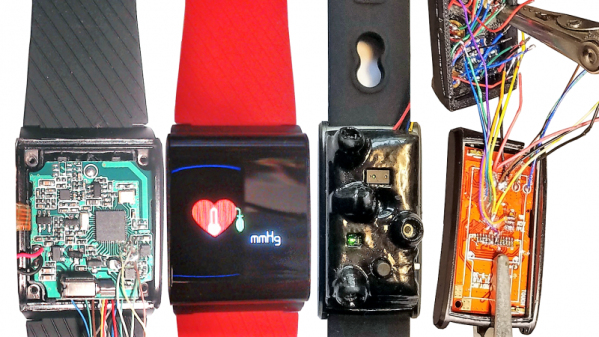
Over the last few years, [Curt White] of the Child Mind Institute has been able to leverage an incredibly cheap but feature-packed platform, the X9 Pro Sports Bracelet, a fitness band that looks more or less like a watch. Stuffed with an ARM Cortex processor, OLED screen, accelerometer, pulse sensor, and a ton of other stuff, the $35 wearable is a hacker’s dream. And hack it he did. One version of the bracelet is called Tingle, which is used to detect and avert body-focused repetitive behaviors (BFRBs), compulsive disorders that can result in self-harm through pulling at hair or pinching. The Tingle is trained to recognize the motions associated with these behaviors and respond with haptic feedback through the vibration motor. Another hacked X9 was attached to a dental retainer and equipped with sensors to monitor respirations intraorally, in an attempt to detect overdoses. It’s fascinating stuff, and the things [Curt] has done with these cheap fitness bands is mighty impressive.
This project is yet another entry in the 2018 Hackaday Prize, which is currently in the Robot Modules phase. Got an idea for something to make robots easier to build? Start a project page on Hackaday.io and get entered. Maybe your module will even feature a hacked fitness tracker.
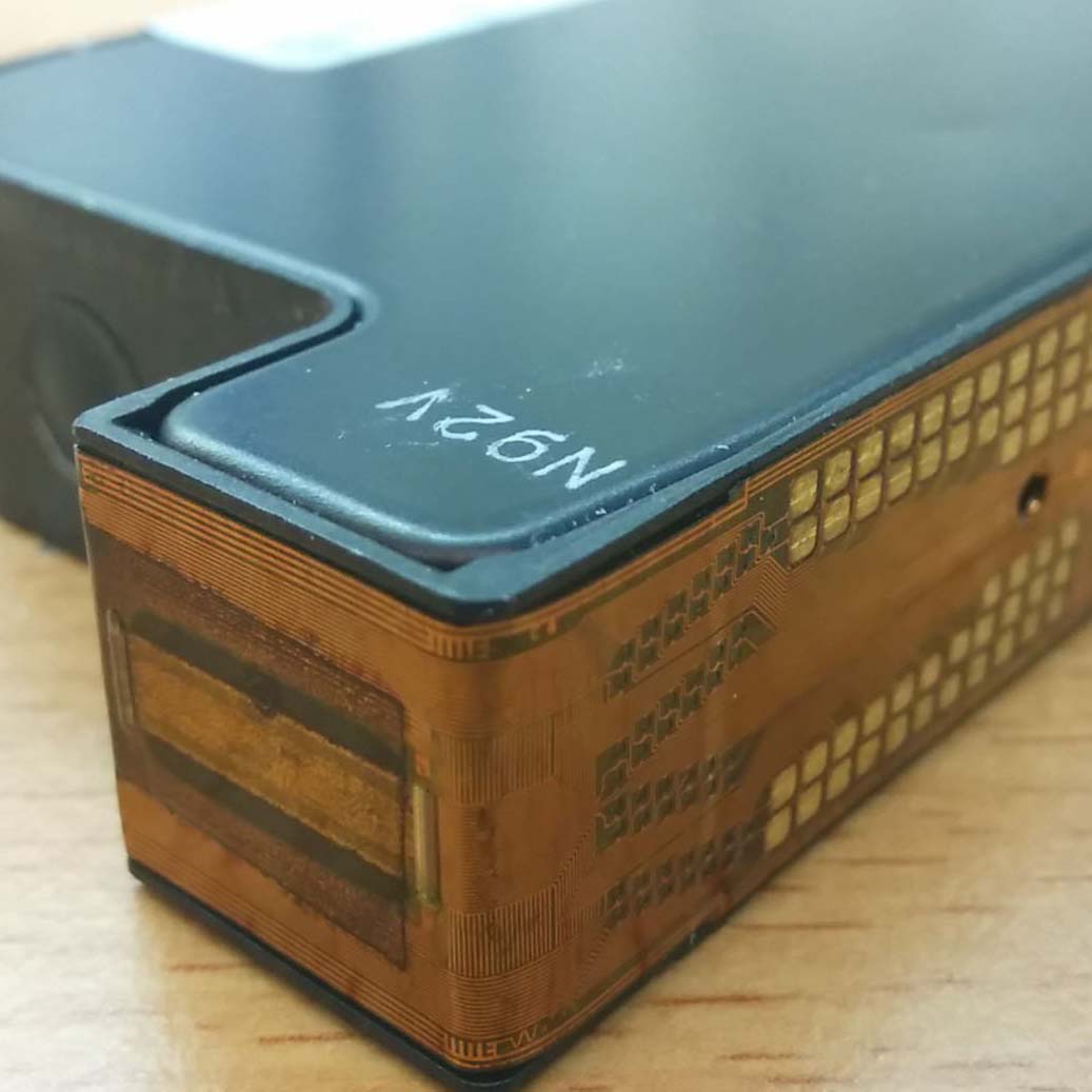
For his Hackaday Prize entry, [Ted Yapo] is building a Robot Radar Module breakout board. His design uses the A111 60 GHz pulsed coherent radar (PCR) sensor from Acconeer AB (New Part alert!) .
The A111 is a low power, high precision sensor ideal for use in object detection or gesture sensing applications. The BGA package is tiny – 5.5 mm x 5.2 mm, but it does not appear very difficult for a hacker to assemble. The sensor includes an integrated baseband, RF front-end and Antenna in Package so you don’t have to mess with RF layout headaches. Acconeer claims the sensor performance is not affected with interference from noise, dust, color and direct or indirect light. Sensing range is about 2 m with a +/- 2 mm accuracy. And at just under $10 a pop for 10 units or more, it would make a nice addition to augment the sensor package on a Robot.
To get started, [Ted] is keeping his design simple and small – the break out board measures just 32 mm x 32 mm. The radar sensor itself doesn’t require any parts other than a crystal and its loading capacitors. A LDO takes care of the 1.8 V required by the A111. Three 74LVC2T45 chips translate the SPI digital interface from 1.8 V to external logic levels between 1.8 V to 5 V. The three level translation chips could possible be replaced by a single six or eight channel translator – such as one from the TXB series from TI. For his first PCB iteration, [Ted] is expecting to run in to some layout or performance issues, so if you have any feedback to give him on his design, check out his hardware repository on Github.
Acconeer provides a Getting Started guide for their Evaluation Kits, which includes a detailed Raspberry-Pi / Raspbian installation and an accompanying video (embedded after the break) targeted at hackers. We are eagerly looking forward to the progress that [Ted] makes with this sensor breakout. Combined with LiDAR ToF sensor breakout boards, such as the MappyDot, it would be a great addition to your robot’s sensing capabilities.
Right now, we’re running the greatest hardware competition on the planet. The Hackaday Prize is the Academy Awards of Open Hardware, and we’re opening the gates to thousands of hardware hackers, makers, and artist to create the next big thing.
Last week, we wrapped up the first challenge in this year’s Hackaday Prize. We’re now happy to announce twenty of those entries that have been selected to move to the final round and have been awarded a $1000 cash prize. Congratulations to the winners for the Open Hardware Design Challenge portion of the Hackaday Prize. Here are winners, in no particular order:
Open Hardware Design Challenge Hackaday Prize Finalists:
The Oasis 3D Printer repurposes HP ink cartridges to build a powder-baseed 3D printer
Just take a look at these projects. They are the best of the best, and there’s still more to come. We enjoyed seeing projects that repurpose off-the-shelf technology to vastly extend the capabilities of home manufacturing with the Oasis 3DP. This project from [Yvo de Haas] takes ink cartridges from HP printers and uses it to build a powder-based 3D printer. That’s something that really hasn’t been done in the world of homebuilt 3D printers, and the Oasis 3DP already has working hardware. It truly is one of the more interesting projects we’ve ever seen, and not just because [Yvo] is dealing with dozens of tiny micro pumps squirting binder out of microscopic nozzles.
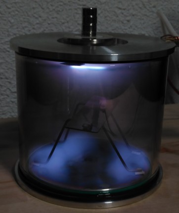
But that’s not all. There were hundreds of projects entered in the Hackaday Prize for this round, and our only regret is that we could only pick twenty winners for the Open Hardware Design Challenge. Just check out Semiconductors @ Home, a project from [Nixie] — it’s a project trying to make sand blink. [Nixie] is building all the tools to make semiconductors at home. Being able to build a simple FET is amazing, and to do that you need a fume hood to contain the dangerous hydrofluoric acid, a vacuum chamber for sputtering deposition, and a fancy oven with a controlled atmosphere. These tools are [Nixie’s] entry in the design challenge. This isn’t your garden variety hardware hacking; this is advanced hardware hacking.
Not impressed with DIY semiconductors? You’re a terrible person, but okay. How about an easy way to read rotary encoders? [fattore.saimon] and [Atikaimu] are building an I2C Encoder, an easy way to read multiple rotary encoders with just two microcontroller pins. Reading rotary encoders is one of the deceptively difficult tasks in electrical engineering; you really need some interrupts to do it right, and a microcontroller really only has a few of those to spare. [fattore] and [atikaimu]’s project does away with that problem, and puts rotary encoders on a board that can be read with a normal I2C bus. This means anyone can add a dozen rotary encoders to any project easily. Did anyone say MIDI controllers? Yes, that is possible. Everything from musical instruments to impressive control panels is possible with the I2C encoder, and it’s all Open Hardware.
Are you still not entertained? [Carl Bugeja] built a motor out of a PCB. Over the last decade, the price of custom fabricated printed circuit boards has dropped precipitously, and that means anyone can experiment with copper foil and fiberglass. [Carl] figured that since you can put coils on a PCB, you could also make a motor. While we’re only looking at a 1 Watt motor here, this is a brushless motor made out of printed circuit boards. It’s amazing, you’ve never seen it before, and we have absolutely no idea how many uses people will find a use for this amazing technology.
These are the winners of the Open Hardware Design Challenge in the Hackaday Prize, and we have a fondness for Open tools that are capable of building even more open hardware. If you want an example of that, you need only look at the Arcus-3D-P1 from [Daren Schwenke]. This is a project to add a lightweight pick and place head to any 3D printer. Below a certain size, a pick and place machine is necessary to create electronics, and almost everyone has a 3D printer these days. The Arcus-3D-P1 is an attachment for any 3D printer to turn it from a CNC hot glue gun into a machine that builds electronics. It’s Open Hardware, and hardware that creates hardware. It’s astonishing, and it’s happening on Hackaday.io.
Congratulations to all who entered the first challenge, and the twenty excellent entries that are moving to the finals. We can’t wait to see what other projects will make it to the finals in the Hackaday Prize, the greatest hardware competition on the planet.
Who will win the 2018 Hackaday Prize?
Who will win the Hackaday Prize? These finalists in the Open Hardware design challenge are now in the running for the final round of the Hackaday Prize where they will have the chance to win the Grand Prize $50,000 USD. That doesn’t mean you still can’t get in on the action; there are four more challenges left in the Hackaday Prize.
Right now, we’re in the middle of the Robotics Module Challenge, and after that, we’ll launch into the Power Harvesting Challenge, the Human Computer Interface Challenge, and finally the Musical Instrument challenge. There’s still time to win your place among the hardware greats, so start your Hackaday Prize entry now.
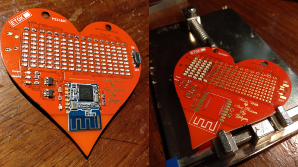
What’s a hacker to do to profess his love for his dearest beloved? [Nitesh Kadyan] built his lady-love this awesome LED pendant – the LED BLE Hearty Necklace Badge.
The hardware is pretty vanilla by today’s hacker standards. An ATMega328p does most of the heavy lifting. An HM-11 BLE module provides connection to an Android mobile app. Two 74HC595 shift registers drive 16 columns of red LEDs and a ULN2803 sinks current from the 8 rows. The power section consists of a charger for the 320mAh LiPo and an LDO for the BLE module. All the parts are SMD with the passives mostly being 0603, including the 128 LEDs.
128 LEDs soldered wrong way around
[Nitesh] didn’t get a stencil made for his first batch of boards, so all the parts were painstakingly soldered manually and not in a reflow oven. And on his first board, he ended up soldering all of the LED’s the wrong way around. Kudos to him for his doggedness and patience.
The Arduino code on the ATmega is also quite straightforward. All characters are stored as eight bytes each in program memory and occupy 8×8 pixels on the matrix. The bytes to be displayed are stored in a buffer and the columns are left shifted fast enough for the marquee text effect. The Android app is built by modifying a demo BLE app provided by Google. The firmware, Android app, and the KiCAD design files are all hosted on his Github repository.
[Nitesh] is now building a larger batch of these badges to bring them to hillhacks – the annual hacker-con for making and hacking in the Himalayas. Scheduled for later this month, you’ll have to sign up on the mailing list for details and if you’d like to snag one of these badges. To make it more interesting, [Nitesh] has added two games to the code – Tetris and Snakes. Hopefully, this will spur others to create more games for the badge, such as Pong.
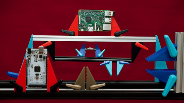
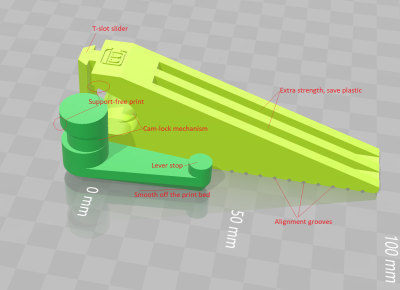
The typical hacker can never say no to more tools. And when it comes to clamps, one just can’t have enough of them. From holding small PCB’s to clamping together large sheets of plywood, you need a variety of sizes and quantities. So it would be pretty neat if we could just 3D print them whenever needed. [Mgx3d] has done that by designing 3D printable bar clamp jaws with a quick release mechanism that can be used with standard T-slot aluminum extrusion. This allows you to create ad-hoc bar clamps of any size and length quickly.
The design consists of two pieces – the jaw and its quick release lever, and does not require any additional parts or fasteners for assembly. Both pieces can be easily 3D printed without supports. The quick release lever is a simple eccentric cam design which locks the jaw in place by pushing down on the extrusion. The design is parametric and can be easily customized for different sizes, either in OpenSCAD or via the online customizer. The online customizer supports Misumi 15 mm and 20 mm extrusion, 1″ 1010-S and 20 mm 20-2020 from 80/20 Inc., 15 mm from OpenBeam and 10 mm from MicroRax. But it ought to be easy to create fresh designs in OpenSCAD. Check out the video after the break to see the bar-clamps in action.
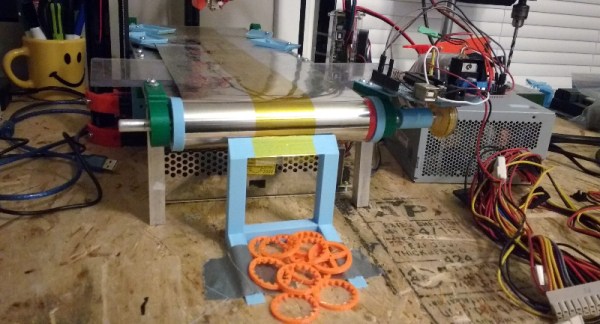
3D printers can be used in a manufacturing context. This might be surprising for anyone who has waited hours for their low-poly Pokemon print, but for low-volume plastic parts, you can actually run a manufacturing line off a few 3D printers. The problem with 3D printers is peeling the print off when it’s finished. If only there were a conveyor belt solution for a bed that wasn’t forgotten by MakerBot.
[Swaleh] may have a solution to the problem of un-automated 3D printers. He’s designing the WorkHorse 3D, a printer that uses a conveyor belt as a bed. When the print is finished, the conveyor belt rolls forward, depositing a printed part in a bin. It’s the solution to truly automated printing.
The use of conveyor belts to automate a batch of 3D prints isn’t a new idea. Way back in the Before Time, MakerBot released the Automated Build Platform, and used it in production to print off parts for Thing-O-Matics. This bit of Open Hardware was left by the wayside for some reason, and last year saw the invention of a new type of conveyor belt-based printer, The Infinite Build Volume Printer (for lack of a better name) from [Bill Steele]. This printer angles the print bed at 45 degrees, theoretically allowing for prints that are infinitely long. This idea was turned into the Printrbot Printrbelt, and the Blackbelt 3D printer was made public around the same time.
[Swaleh]’s printer is not of the infinite build volume variety. Instead of concentrating on creating long beams, most of the engineering work has gone into making a printer that’s designed to just push prints out. The conveyor belt bed is flat — and may unfortunately infringe on the MakerBot patents — but if you want a printer that’s designed to dump parts out like a very slow injection molding machine, this is the design you want.
The print queue application for this project is just a simple desktop app that serves as a buffer for G-code files. The app sends one G-code file off to the printer, rolls the bed forward, and queues up the next part. It’s simple, yes, but there aren’t too many things that do this now because there aren’t too many printers built to be factories. It’s impressive, and you can check out a few videos of this printer in action below.


 The typical hacker can never say no to more tools. And when it comes to clamps, one just can’t have enough of them. From holding small PCB’s to clamping together large sheets of plywood, you need a variety of sizes and quantities. So it would be pretty neat if we could just 3D print them whenever needed. [Mgx3d] has done that by designing