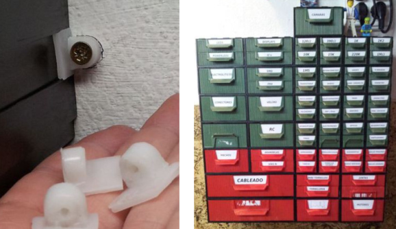
PCB Agitator From A Broken CD-ROM Drive

pcb-agitator

Etching PCBs goes a lot better if you agitate the solution in order to carry away the dissolved copper and get fresh etchant to the area. With that in mind [Rohit Gupta] designed a mechanism in Sketch Up before realizing he was going about it the hard way. He ended up basing his agitator on a broken CD-ROM drive instead of starting from scratch.

He uses the CD sled from the drive, ditching the lens and its support structure. To get direct access to the motor that drives the tray he uses an L293D H-bridge chip. This is controlled by an MSP430G2231 microcontroller. The driver board seen in the upper right includes a voltage regulator, three status LEDs, and one user input switch. Once triggered, the sled will move back and forth, contacting an old mouse microswitch which acts as the limiting switch. We find it entertaining that [Rohit] prototyped the circuit on a breadboard, then used that success to etch the final circuit board (shown in the video below).

If you’ve been following the hacker creed and never getting rid of any junk you’ll have no problem finding a donor drive to make one of your own. But just in case you can’t get a hold of this hardware a similar agitator can be built using a hobby servo.

Continue reading “PCB Agitator From A Broken CD-ROM Drive”

Git With Eagle: Add Meaning to Diff

a-glimpse-of-git-with-eagleWe love Git. We know everyone has their favorite version tracking tools. But even those that don’t care for Git should see the value of getting meaningful Diff data from tracking Eagle layout files.

Was that last sentence just gibberish to you? Let’s take a step back. A few years ago it was impossible to use version control with Eagle at all because the schematic and PCB layout software used to save its files as binaries. But then Cadsoft transitioned to saving Eagle files as XML. This opened the door for things like scripting to rename parts en masse and to track the files under version control. One problem with the latter has been that performing a Diff on two different versions of a file results in XML changes that are probably not human readable. [Patrick Franken] wrote this script to add at least a glimmer of meaning.

We’d love to see some kind of side-by-side highlighting on the schematic or board renderings themselves. But that’s quite a ways off if we ever actually see it. For now his script will take the Diff and print out the tables seen above denoting which types of changes were made from one version to the next. It’s a start, and we hope it inspires even more work in this area.

A Pick And Place Tool From Medical Equipment

neb

A vacuum tool is an invaluable tool if you’re working with tiny SMD parts, and even with tweezers you might have a hard time placing these nearly invisible components on their pads for soldering. One tool that’s really great for these parts is a vacuum pen, usually made from an old aquarium air pump. [Jon] may have found a much more suitable piece of equipment to scavenge for a vacuum pen build – a nebulizer.

Nebulizers provide asthmatics with low pressure, low volume air to atomize medication for inhalation. Inside the nebulizer is a small diaphragm pump, just like the small aquarium pump teardowns we’ve seen. In just five minutes, [Jon] tore his thrift store nebulizer apart and reversed the flow of air, turning something that blows into something that sucks.

After the suction part of the build was finished, [Jon] needed a way to pick up small components. He did this by blunting a large hypodermic needle and fastening it to the end of a Bic pen with heat shrink tubing. After drilling a small hole in the pen body, he had a very nice looking SMD vacuum pump.

Making A HP Frequency Counter More Accurate

[Gerry] built his own high stability timebase add-on for his HP 53131 frequency counter. This project started out after [Gerry] built a rubidium 10 MHz standard for his lab. Upon connecting the standard to the frequency counter for calibration, he found that the HP 53131 had an awful internal oscillator. The official high stability timebase add-on from HP cost about $1000, and he was determined to do better.

Using a second hand OCXO as the oscillator, he designed his own add-on module. OCXO modules pack a crystal oscillator in a thermal chamber. Since temperature fluctuation causes drift in crystal oscillators, an OCXO controls the temperature to keep the frequency constant. They can be bought second hand on eBay for under $30.

The PCB design for the module can accommodate a variety of OCXO modules. It uses a high speed comparator and a high stability 5 volt reference to provide the clock signal to the counter. A DAC is used to calibrate the oscillator. By keeping the same DAC as the original counter, the add-on board can be calibrated using the front panel of the device.

The project is a drop in replacement for HP’s $1000 module for a fraction of the cost. [Gerry]’s write up has all the details you’ll need to build your own.

Continue reading “Making A HP Frequency Counter More Accurate”

Logging Two Multimeters At (nearly) The Same Time

log-two-multimeters-at-one-time

It’s pretty common to have at least a couple of meters around to measure different values of a circuit at the same time. Where [Emilio P.G. Ficara] ran into a problem was logging the data from both at once. These Fluke meters have a serial-out, but his computer only has a single serial-in port. He cracked open one of the meters and figured out how to log data from both at the same time.

A lot of folks would look to a microcontroller to solve this problem. You use the chip to pull from each meter simultaneously and report back to a computer (or just dump the values onto an SD card). But this solution is a simple mechanical connector and a bit of creative programming. The way the serial output is set up on these meters they won’t interfere with each other as long as they’re read one at a time. [Emilio] wired them up as seen above, using his own software to manage the pins of the serial port. The example output he posted shows readings from the meters taken within about a tenth of second from each other. That should be good enough for most applications.

The Straddler Makes AVR Breadboarding Truly Plug And Play

the_straddler_avr_programmer

It’s not that breadboarding AVR circuits is difficult. But you have to admit that it takes some time to set everything up. We don’t label the top of our DIP chips so that you know what each pin does just by looking. Which means that wiring up the programmer involves pulling out the datasheet. [Vinnie] found the solution to this problem which is to make one of these interface PCBs for each AVR chip family. The long pins make it easy to drop over the top of your microcontroller, which is where the name comes from.

His first stab at the idea was just a hunk of home etched PCB which broke out the programming pins into the 6-pin ICSP standard. This second rendition uses the 10-pin standard and adds a few extras into the mix. He included decoupling capacitors which need to be used in every circuit anyway. There’s a crystal along with its load capacitors. This clock source is a snap to enable by burning some fuses. If you choose to use the internal oscillator instead this hardware won’t interfere. The LED is used to get you up and running with blinky firmware as quickly as possible. He plans to add jumper in the next revision which can disconnect this components from the I/O pin. Now you just need to add a 10-pin header to that USB keyboard AVR programmer and you’re in business.

Connecting An Old Scope To A Computer

Scope

A friend of [Michael]’s said his company was getting rid of some old lab equipment and asked him if he wanted a very large and very old digital storage oscilloscope. A ‘hell yes’ and we’re sure a few beers later, [Michael] found an old Gould 200 MHz four-channel scope on his bench. Even 20 years after its production it’s still a capable tool, but the serial ports on the back got [Michael] wondering – would it be possible to plot the screen of the scope on his computer?

The scope has three ports on the back – GPIB, miscellaneous I/O, and RS423. The latter of those ports is similar enough to RS232 that a USB to Serial converter just might work, and with the help of a null modem cable and a terminal, [Michael] was able to connect to this ancient scope.

In the manual, [Michael] found a the serial commands for this scope. The most useful of these is a command that prints out the contents of the scope’s trace memory as a series of 1-byte integers. With a short bit of PERL programming, [Michael] can create a PDF plot of whatever is on the scope’s screen. It’s formatted perfectly for Gnuplot, MATLAB, or even Excel.

Awesome work, and especially useful given these old scopes are slowly making their way to a technological boneyard somewhere.