Measuring resistance doesn’t seem to be a big deal. Put your meter leads across two wires or terminals and read the value, right? Most of the time that is good enough, but sometimes you need better methods and for those, you need more wires, as [FesZ] explains in his recent video that you can see below.
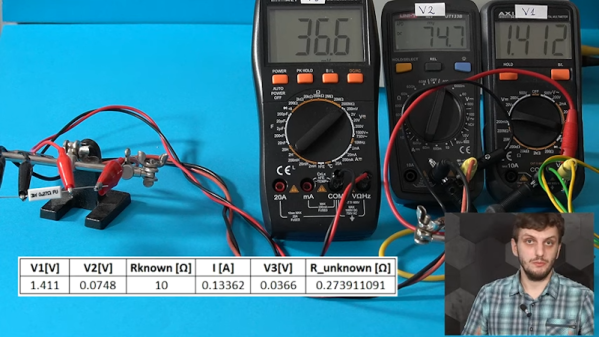
In the usual case, the meter applies a known voltage and measures the current which, by Ohm’s law, gives you the resistance. It is also possible to control the current and measure the voltage — doesn’t matter. [FesZ] shows how many meters measure voltage across a known resistor and the unknown so that a precision voltage or current source isn’t necessary.
But there are a number of problems with this simple method. For one thing, the test leads have resistance as well. So some voltage will drop across them, contributing to measurement error. Sure, that extra 0.5 ohms won’t matter if you are looking at a 100K resistor, but if you are trying to measure, say, the heated bed of a 3D printer, that extra 0.5 ohms is a large percentage of the total measurement.
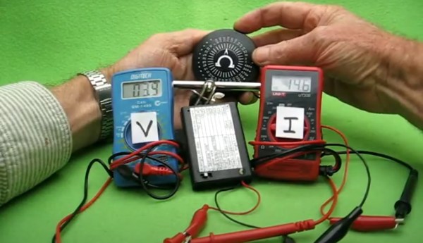
 Bench meters for lab use often support 4-wire measurements. As [FesZ] shows, this method measures three different voltages to try to negate some of the measurement errors. We liked that he used three different meters to show how it works and the difference between a 2-wire and 4-wire measurement on a small resistor.
There’s an even stranger method using 3 wires to save on wiring for, say, a sensor a long distance away. There are actually at least two ways to use 3 wires, and the video covers both of them.
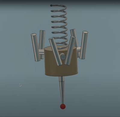
For measuring resistors in a circuit, though, you need a whopping six wires. This technique uses the two extra wires to control a balance voltage that keeps the current between the unknown resistor and the rest of the circuit at zero. This prevents current flowing except for the measurement current. You’ll see a simulation of how this works in the video.
We’ve looked at 4-wire measurements before if you want some practice simulations to try. Probes for this measurement are a popular project, too.
Continue reading “How Many Wires Do You Need To Measure A Resistor?”

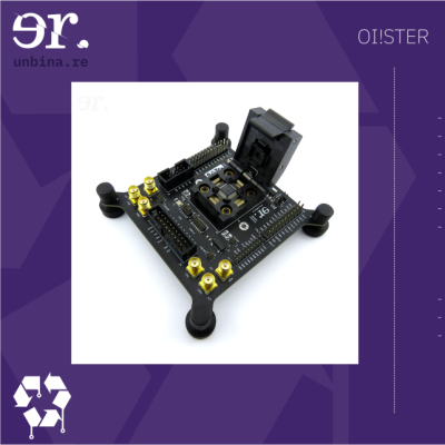 Unbinare’s tools are designed to work in harmony with each other, a requirement for any productive reverse-engineering effort. OI!STER is a general-purpose salvaged MCU research board, with sockets to adapt to different TQFP chip sizes. This board is Maurits’s experience in reverse-engineering condensed into a universal tool, including a myriad of connectors for different programming/debugging interfaces. We don’t know the board’s full scope, but the pictures show an STM32 chip inside the TQFP socket, abundant everywhere except your online retailer of choice. Apart from all the ways to break out the pins, OI!STER has sockets for power and clock glitching, letting you target these two omnipresent Achilles’ heels with a tool like ChipWhisperer.
![USB to Dupont adapter by [PROSCH]](https://hackaday.com/wp-content/uploads/2022/01/2022-01-01-USB-to-DuPont-adapter-feat.jpg?w=600&h=450)