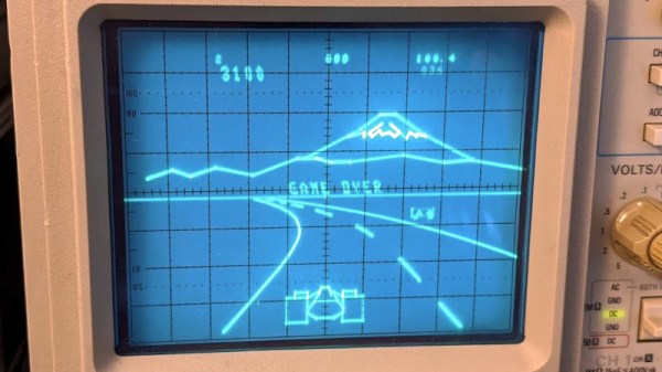
You’ve always wanted a game console at your bench, but maybe you haven’t had space for a monitor or TV set? Wouldn’t it be useful if the screen you do have on your bench could also play games? [Tube Time] has fixed this problem, with Scopetrex, a vector graphic console for your oscilloscope. In fact, it’s better than just a console, because it’s a clone of the legendary Vectrex, the vector-based console with built-in CRT screen from the 1980s.
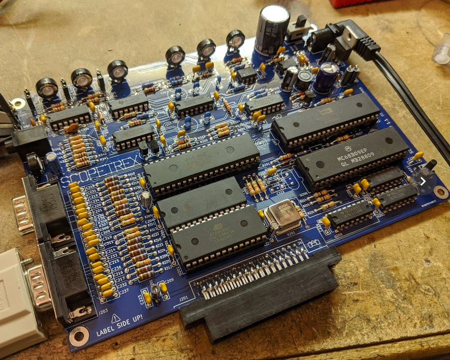
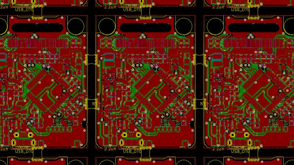
The board itself is a slightly enhanced version of the original, offering not extra functionality but the ability to substitute some of the parts for more easily found equivalents. It gives full control over display size and brightness, can use the cheaper 6809E processor and AY-3-9810 sound chip if necessary, and only needs a single 5 volt supply. There’s also a custom controller board, which is handly Vectrex-compatible. All you will need to play Vectrex games on your ‘scope once you’ve built this board, are a copy of the Vectrex ROM, and some games.
The Vectrex holds an enduring fascination for our community, and has appeared here many times. Particularly memorable is a CRT replacement, and then of course there’s the never-released mini Vectrex prototype.
Thanks [Justin List] for the tip.