A mill is one of those things that many hackers want, but unfortunately few get their hands on. Even a low-end mill that can barely rattle its way through a straight cut in a piece of aluminum is likely to cost more than all the other gear on your bench. A good one? Don’t even ask. So if something halfway decent is out of your price range, you might as well throw caution to the wind and build one.
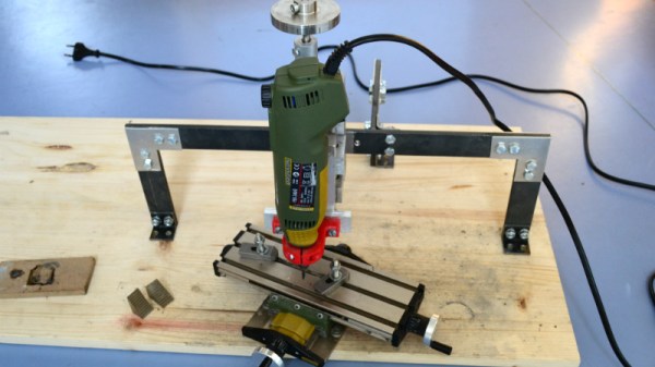
 That’s more or less the goal behind this extremely basic three axis mill built by [Michael Langeder]. Designed around a cheap rotary tool, it’s hard to imagine a more simplistic mill. Almost all the components are stuff you could pick up from the local hardware store, or probably even the junk pile if you were really in a pinch. It won’t be the best looking piece of gear in your shop, but it’s good enough to learn the basics on and just might be able to bootstrap a second-generation mill RepRap-style.
Made out of scrap blocks of aluminum and some threaded rod, the Z axis itself represents the bulk of the work on this project. It gives the user fine control over the height of the rotary tool by way of a large knob on the top. It’s held over the work piece with some flat steel bars and corner brackets rather hastily cut out of aluminum sheet.
While the tool holder is 3D printed, you could probably hack something up out of a block of wood if you didn’t have access to a printer. The only part of the mill that’s really “cheating” is the cross slide table, but at least they can be had for relatively cheap. If you really wanted to do this with junk bin finds, you could always replicate the Z axis design for X and Y.
If you’re not looking for something quite so austere, we’ve covered slightly more advanced DIY mills in the past. You could always go in the opposite direction and put a cross slide vise on your drill press, but do so at your own risk.