A proper soldering iron is one of the fundamental tools that a good hacker needs. Preferably one that has a temperature control so it can handle different types of solder and connectors.
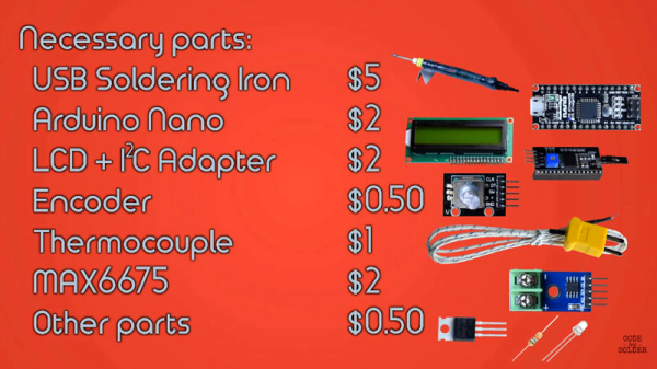
Decent soldering stations aren’t cheap, but [Code and Solder] show you how to make one for about $15 in parts. This uses a cheap non-temperature-controlled USB soldering iron, an Arduino and a few other bits that they got from AliExpress. The plan is to add a thermocouple to the soldering iron, and let the Arduino control the temperature. A rotary dial and LCD screen control the set-point, and the Arduino switches the feed to the heating element on and off through the FET.
It’s not the cleanest build in the world, and these USB soldering irons aren’t suitable for large joints or long soldering jobs, but it’s a neat little hack for the builder on a budget. We’ve seen teardowns of these rather neat little USB soldering irons before, but this is an interesting way to expand its capabilities.