Tools Of The Trade – Solder Paste Dispensing

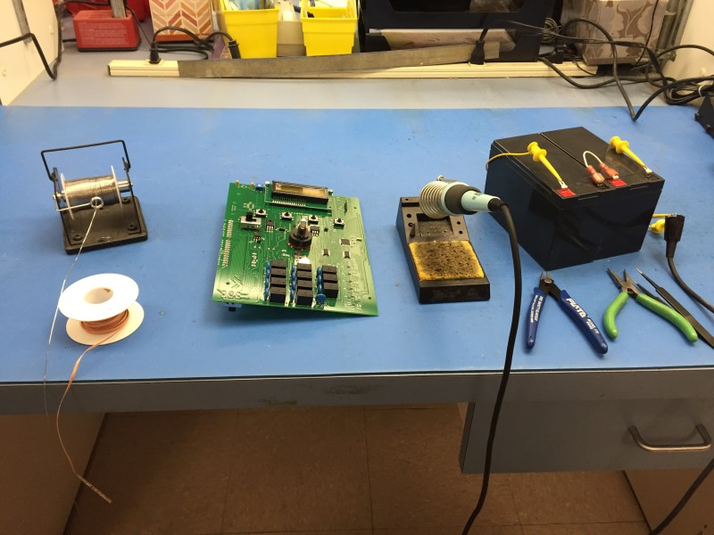
The general process of circuit board assembly goes like this: You order your PCBs. You also order your components. For surface mount components, you apply solder paste to the pads, put the components on top, and then heat the board up so the solder paste flows and makes a bond. Then for through hole components you put the leads through the holes, and solder them with an iron or a solder wave or dip. Then you do an inspection for defects, program any microcontrollers, and finally test the completed board to make sure everything runs.

The tricky part is in volumes. If you’re only doing a few boards, it’s usually easiest to assemble them by hand. In the thousands you usually outsource. But new tools, and cheap hacked tools, have made it easier to automate small batches, and scale up into the thousands before outsourcing assembly.

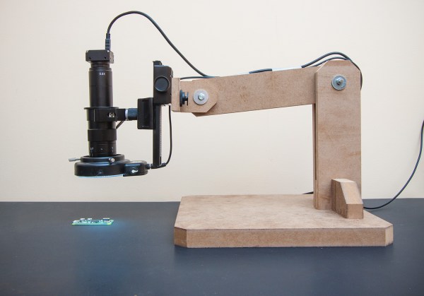
In this new series which we’re calling Tools of the Trade we’ll be covering a variety of tools used for building products, and we’re starting with circuit board assembly. Let’s investigate our tools of the trade: solder paste dispensing. Continue reading “Tools Of The Trade – Solder Paste Dispensing”

Tindie Opens A Flea Market For Tools, Components, And Other Gear

We like to pop into electronics flea markets and swap meets at every chance we get. Last month [Brian] made it to the ham swap meet at Northrup Grumman held in Redondo Beach. I had a great time a couple of years back at the Electronics Flea Market held at De Anza College. Physical proximity to one of these nearly-mythical events is, unfortunately, required. If only the Internet offered a solution to this problem…

The fact that you’re reading Hackaday puts you into one of three categories: you wish you had a lot more tools, you’re on the way to a well-stocked workshop, or you’re trying to pass on your shop surplus to someone who will love it like you do. There’s now a perfect solution for the buy-upgrade-horde cycle we all inevitably fall into: the Tindie Flea Market. If you use something to make hardware, this is going to be the place to buy or sell it.

tindie-flea-market-thumbHas that starter scope been collecting dust since you picked up not one, but two better models? We know you can’t part with it unless you know it’s not going to be thrown out, and this is the chance to find not just a good home, but an owner that will use and cherish it. This goes for all kinds of great tools. After all, how do you find someone to take that pick and place off of your hands?

At launch, the Tindie Flea Market categories will include Adapters and Cables, Audio and Video, Batteries and Power, Bulk Components, Equipment, Fasteners, RC, and Small Tools. Maybe I’ll finally be able to find a home for that tube of power transistors I ordered years ago in the wrong package — and maybe even that long tape of EEPROM that I ordered in 1.8v instead of 3.3v. Time to start my listings and keep good stuff out of the landfill. Yet another great reason we were so happy to welcome Tindie to the Hackaday family.

Arduino RF Network Analyzer

What do you get when you combine a direct digital synthesis (DDS) chip, a power detector, and an Arduino? [Brett Killion] did make that combination and wound up with a practical network analyzer.

The project uses an Analog Devices AD9851 DDS chip clocked at 180 MHz which will output a sine wave at any frequency from 0 Hz and 72 MHz. A Butterworth low pass filter processes the DDS signal and then feeds a two-transistor amplifier. The circuit will output about 0dBm into 50 ohms. The power detector is an Analog Devices AD8307 along with a 50-ohm input load. There is no filtering on the power detector so it can measure from very low frequencies to 500MHz.

Continue reading “Arduino RF Network Analyzer”

Dual UART/I2C Breakout Goes Both Ways

[Jesus Echavarria] sent us a link to this cute little tool that he’s built. It’s a dual USB-to-I2C-or-UART adapter, with a few more oddball features thrown in for good measure. If you were electronics Batman, you’d have this on your utility belt.

[Jesus] originally designed the board because he wanted to sniff a bi-directional UART conversation using his computer, and get it all done in inexpensive hardware with minimal fuss. So he looked to the Microchip MCP2221 chip, which is an inexpensive USB to serial and I2C chip, but with some extras. In particular, it’s got four GPIOs, a ten-bit ADC and a five-bit DAC with selectable reference voltage, and it’s all controllable over USB. And [Jesus]’s board has two of them.

Implementing USB on a microcontroller isn’t always that much fun, so we can see why he took the straight-ahead hardware approach. And as a side benefit, he gets all the other kooky functionalities that the chip brings. And we have been introduced to what looks like a neat chip to use in USB and microcontroller projects. We’re going to put one in our next random chip order.

PCB Laminator Is Its Own Project

One of the easiest ways to make PC boards at home is to use the toner transfer method. The idea is simple: print the artwork using a laser printer and then use a clothes iron to transfer the toner from the paper to a clean copper clad board. The toner is essentially plastic, so it will melt and stick to the board, and it will also resist etchant.

There are several things you can do to make things easier. The first is the choice of paper. However, the other highly variable part of the process is the clothes iron. You have to arrange for the right amount of heat and pressure. If you don’t do a lot of boards, you’ll probably have to make several passes at getting this right, scrubbing the reject boards with acetone and scouring pads to clean them again.

[Igor] had enough of the clothes iron and knew that other people have used lamination machines to get the toner off the paper and on the blank board. He started with a commercial laminator but hacked it for PID control of the temperature and made other improvements.

Continue reading “PCB Laminator Is Its Own Project”

Icestudio: An Open Source Graphical FPGA Tool

If you’ve ever worked with FPGAs, you’ve dealt with the massive IDEs provided by the vendors. Xilinx’s ISE takes about 6 gigabytes, and Altera’s Quartus clocks in at over 10 gigs. That’s a lot of downloading proprietary software just to make an LED blink.

[Jesús Arroyo]’s Icestudio is a new, graphical tool that lets you generate Verilog code from block diagrams and run it on the Lattice Semi iCEstick development board. A drag and drop interface lets you connect IOs, logic gates, dividers, and other elements. Once your block diagram is ready, a single button press downloads the code to the iCEstick.

Under the hood, Icestudio uses IceStorm, which we’ve discussed on HaD in the past, including this great talk by [Clifford], Icestorm’s lead. For the GUI, Icestudio uses nw.js, which spits out JSON based on the block diagram. This JSON is converted into a Verilog file and a PCF file. The Verilog is used to create the logic on the FPGA, and the PCF is used to define the pin configuration for the device. Clicking on selected modules reveals the generated Verilog if you want to know what’s actually going on.

It’s experimental, but this looks like a neat way to get started on FPGAs without learning a new language or downloading many gigs of toolchains. We’re hoping Icestudio continues to grow into a useful tool for education and FPGA development. A demo follows after the break.

[Thanks to Nils for the tip!]

Continue reading “Icestudio: An Open Source Graphical FPGA Tool”

Clearly The Best Way To Organize SMD Parts

Have some plexiglas (acrylic) leftovers lying around? Well, they could be put to good use in making this SMD organizer. It comes in handy if you deal with a lot of SMD components in your work. No longer will you waste your time trying to find a 15K 1206 resistor, or that BAS85 diode… or any other component you can think of soldering on the PCB. The basic idea is fairly straightforword, which helped keep this short.

2SMD resistors are packed in thick paper tapes that don’t bend easily, and thus need larger containers than other components, which are packed mainly in flexible PE tapes. The first version of this organizer was built with a 96mm diameter space for resistors and 63mm diameter for other components, but it seems that there is no need for such large compartments. If I were to make it again, I would probably scale everything down to about 80% of it’s current size.

The best way to join all plexiglass parts is to use four M4 threaded rods. There is also a 1.5mm steel rod which holds SMD tape ends in place and helps to un-stick the transparent tape which covers the components. At the top of the organizer there is a notch for paper, used for components labels. Most SMD components are packed in 8mm wide tapes, making the optimal compartment width 10mm. It is not easy to cut the 10mm thick acrylic and get a neat edge – instead, you could use more layers of thin sheets to make the spacers. Using 5mm acrylic you can combine more layers for any width of tape, which contains wider components, like SMD integrated circuits. The only thing that you have to be careful about, is to keep the distance between the thin steel rod and acrylic, which is marked as “2-4mm” on the drawing. It is good if this space is just a few tenths of a millimeter wider than the thickness of SMD tapes.

smd_orthoThe CorelDraw file that can be used for laser cutting the acrylic parts, is available for download. If you scale the profiles, don’t forget to readjust the hole diameters and some other dimensions which have to remain intact. If you have 5mm acrylic pieces, you should probably use two layers of acrylic for every tape (red parts on the drawing). The barrier layers would be made of thin acrylic — for instance 2mm (the blue parts). Edge layers (green) are once again 5mm thick, and there are also the end pieces (yellow), glued to the previous borders and used to “round up” the whole construction and to protect your hands from the threaded rods and nuts.

While you’re building this for your bench, make a vacuum picking tool for SMDs out of a dispensing syringe with a thick needle. It’s a common trick for hackers to use an aquarium air pump, just turn the compressor unit by 180°, so that it creates vacuum instead of blowing the air outside. This process is described by R&TPreppers in the video below.

Continue reading “Clearly The Best Way To Organize SMD Parts”