One of the great things about the Gearing Up challenge of the 2023 Hackaday Prize is that it lets you discover tools that you don’t encounter every day. We had never given much thought to spin coaters, for example, until we saw [Jeroen Delcour]’s neat homebrew example. As it turns out, spin coating has lots of applications in fields like optics, semiconductor manufacturing or even art projects, where a thin, even layer of a material is required on top of a flat substrate.
The basic idea behind a spin coater is simple: you dispense a few drops of a solution containing the material to be deposited on top of the thing you want to coat, then spin the thing around at a constant speed. The balance between the centripetal force and the liquid’s surface tension ensures that the liquid turns into a film with a consistent thickness all across the substrate. The solvent evaporates, and you’re left with a nice solid layer just a few microns thick.
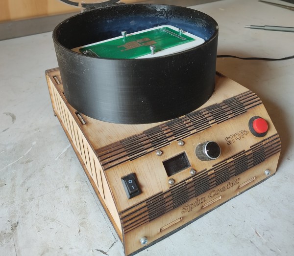
[Jeroen] built his spin coater out of a brushless DC drone motor, a programmable motor controller, and an ESP32. A rotary pushbutton and an OLED form the user interface, allowing the user to select the speed and spin times. The electronics are all mounted inside a laser-cut wooden enclosure, with the motor sticking out the top, surrounded by a 3D-printed splash guard.
Professional spin coating equipment typically comes with a vacuum chuck to hold the sample in place, but [Jeroen] wasn’t too excited about implementing vacuum systems on a spinning platform and decided instead to simply clamp down the sample using screws in a laser-cut piece of acrylic. This works well enough, and is easy to customize for different sample sizes.
In the video embedded below, [Jeroen] experiments with applying a layer of silicone rubber onto a PCB. Spin coating is an essential step when you’re making your own semiconductor devices such as solar cells, though you might also need more complicated equipment such as an electron microscope. [Jeroen]’s spin coater is at least able to process much larger objects than one we saw earlier.
Continue reading “Hackaday Prize 2023: Homebrew Spin Coater Makes Micrometer-Thin Layers”